62
The measured output value is outputted by the BCD code. The relationship between
the displayed value and the output data is as shown below.
In the mantissa part 3-digits display, the 2nd digit of the decimal point is not outputted
(truncated).
When the displayed value is (A. B × 10 ± DC):
Data of A is outputted by the BCD code at the output terminals of A-b0 to A-b3, where
A-b0 is the least significant bit of the four-digit numeral.
Data of B is outputted by the BCD code at the output terminals of B-b0 to B-b3, where
B-b0 is the least significant bit of the four-digit numeral.
Data of C is outputted by the BCD code at the output terminals of C-b0 to C-b3, where
C-b0 is the least significant bit of the four-digit numeral.
Data of D is outputted by the BCD code at the output terminals of D-b0 to D-b3, where
D-b0 is the least significant bit of the four-digit numeral.
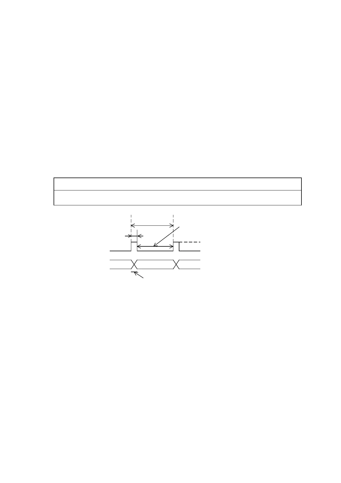
Data valid of the display value (A. B × 10 ± DC) and data rewriting time chart are as
shown in Fig. 10-2 Data valid signal (strobe signal) actuation chart and Fig. 10-3 Data
rewriting time chart-1.
Data are outputted at intervals of about 100 ms, in which data are rewritten at
intervals of 1 ms.
CAUTION:
If data are loaded during data rewriting (DATA VALID Hi), correct displayed values
cannot be loaded.
Fig. 10-3 Data valid signal (strobe signal) actuating chart
In order to terminate all data change within the DATA-VALID signal time, set the
load resistor below the following value:
Load resistance below 48 kΩ at 24 V
Load resistance below 10 kΩ at 5 V
About 100 ms
About 1 ms
Hi(5V)
Hi(5V)
Lo(0V)
Lo(0V)
Earned hours of data
Update time of data