4.3 Controller I/O
24V
EI1
24V
SI0
24V
SI1
24V
EI0
Safety
Safeguard Stop
Emergency Stop
24V 0V
24V
0V
24V
CI1
24V
CI2
24V
CI3
24V
CI0
Configurable Inputs
24V
CI5
24V
CI6
24V
CI7
24V
CI4
4.3.3 General purpose digital I/O
This section describes the general purpose 24V I/O (Gray terminals) and the config-
urable I/O (Yellow terminals with black text) when not configured as safety I/O. The
common specifications in section 4.3.1 must be observed.
The general purpose I/O can be used to drive equipment like pneumatic relays di-
rectly or for communication with other PLC systems. All digital outputs can be dis-
abled automatically when program execution is stopped, see more in part II. In this
mode, the output is always low when a program is not running. Examples are shown
in the following subsections. These examples use regular digital outputs but any con-
figurable outputs could also have be used if they are not configured to perform a safety
function.
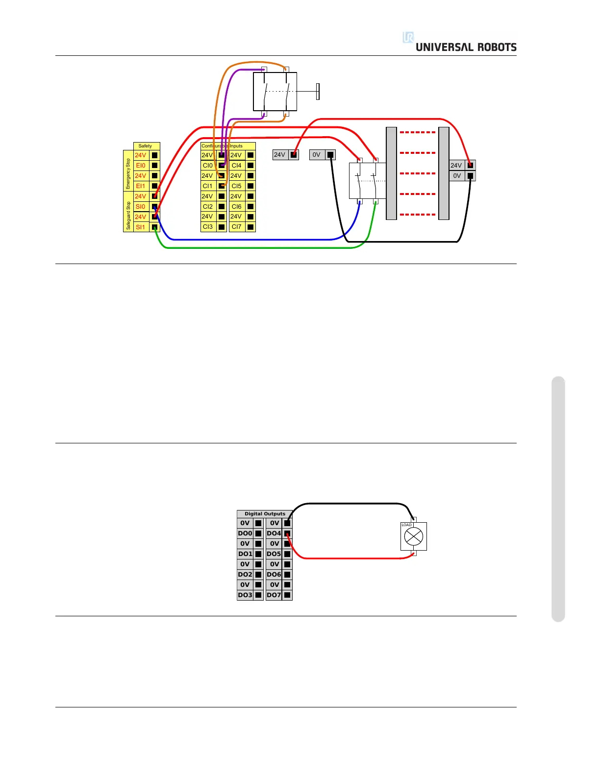
4.3.3.1 Load controlled by a digital output
This example shows how to connect a load to be controlled from a digital output, see
below.
0V
DO1
0V
DO2
0V
DO3
0V
DO0
Digital Outputs
0V
DO5
0V
DO6
0V
DO7
0V
DO4
LOAD
4.3.4 Digital input from a button
The example below shows how to connect a simple button to a digital input.
Version 3.1 (rev. 17782)
Copyright © 2009-2015 by Universal Robots A/S. All rights reserved.
I-27 UR5/CB3