12.12 Installation → Features
12.12 Installation → Features
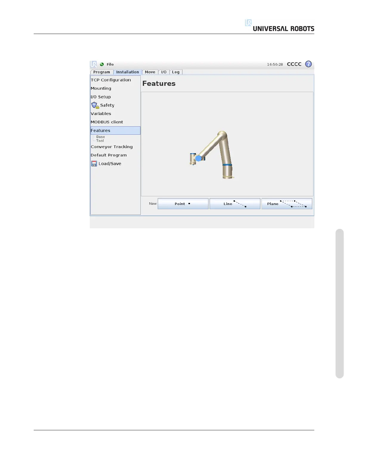
Customers that buy industrial robots generally want to be able to control or ma-
nipulate a robot arm, and to program the robot arm, relative to various objects and
boundaries in the surroundings of the robot arm, such as machines, objects or blanks,
fixtures, conveyers, pallets or vision systems. Traditionally, this is done by defining
“frames” (coordinate systems) that relate the internal coordinate system of the robot
arm (the base coordinate system) to the relevant object’s coordinate system. Reference
can both be made to “tool coordinates” and to “base coordinates” of the robot arm.
A problem with such frames is that a certain level of mathematical knowledge is re-
quired to be able to define such coordinate systems and also that it takes a considerable
ammount of time to do this, even for a person skilled in the art of robot programming
and installation. Often this task involves the calculation of 4x4 matrices. Particularly,
the representation of orientation is complicated for a person that lacks the required
experience to understand this problem.
Questions often asked by customers are for instance:
• Will it be possible to move the robot 4 cm away from the claw of my computerised
numerically controlled (CNC) machine?
• Is it possible to rotate the tool of the robot 45 degrees relative to the table?
• Can we make the robot arm move vertically downwards with the object, let the
object loose, and then move the robot arm vertically upward again?
Version 3.1 (rev. 17782)
Copyright © 2009-2015 by Universal Robots A/S. All rights reserved.
II-33 CB3