Uponor Smatrix Wave T-163
During normal operation a discreet LED on the back of the thermostat
is lit for about 60 seconds if there is a demand for heating or cooling.
The thermostat contains a switch that, if activated during registration,
sends an alarm when the thermostat is removed from the wall. The
alarm is transmitted by radio, causing the related channel LEDs on
the room controller to flash.
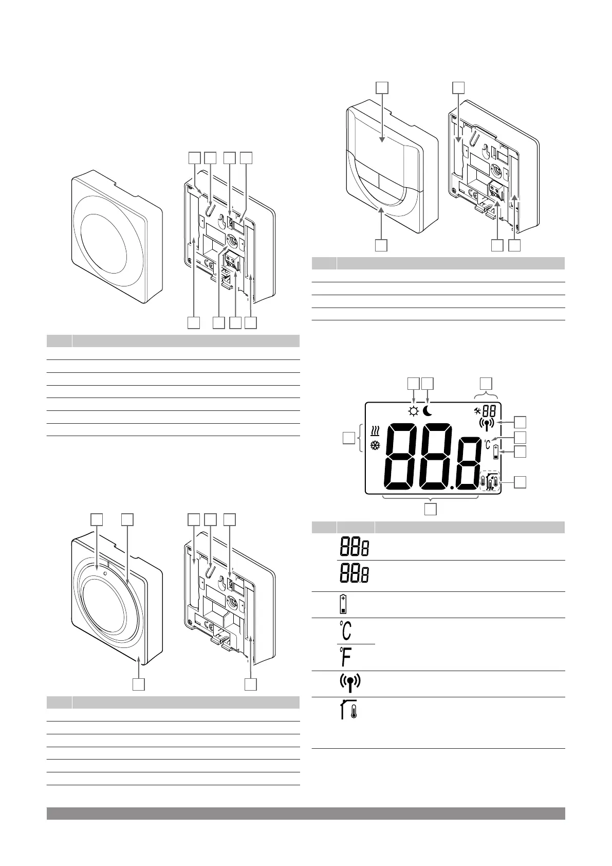
The illustration below shows the parts of the thermostat.
Item Description
A Setpoint temperature potentiometer
B Registration button
C Disable timer switch
D Terminal for external sensor (non-polarised)
E Configuration DIP switches
F Batteries
G Heating/cooling demand LED
Uponor Smatrix Wave T-165
During normal operation a discreet LED on the thermostat is lit for
about 60 seconds if there is a demand for heating or cooling.
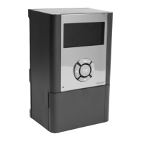
The illustration below shows the parts of the thermostat.
Item Description
A Room temperature setpoint dial control
B Heating/cooling demand LED
C Backlight
D Registration button
E Disable timer switch
F Batteries
Uponor Smatrix Wave T-166
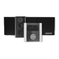
The illustration below shows the parts of the thermostat.
Item Description
A Display
B Buttons
C Terminal for external sensor (non-polarised)
D Batteries
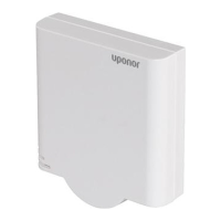
Display layout
The figure shows all possible symbols and characters that can be
shown on the display:
Item Icon Description
A Message field using three alphanumerical characters
Temperature reading using a - or + sign, two digital
characters, a decimal point and a character showing
either 0 or 5
B Low battery indicator
C Temperature unit, shown when the character group A
shows a temperature
D Communication indicator
E Indoor temperature indicator
Remote sensor temperature indicator (RS mode)
The text Err and a flashing sensor icon indicates a
faulty sensor
82
|
Uponor Smatrix Wave PULSE
|
Installation and operation manual