Item Icon Description
Indoor temperature with floor temperature limitation
indicator
The text Err and a flashing floor sensor icon indicates
a faulty sensor
Floor temperature indicator
The text Err and a flashing floor sensor icon indicates
a faulty sensor
Outdoor temperature indicator
The text Err and a flashing outdoor sensor icon
indicates a faulty sensor
F Settings menu
Settings menu number
G Heating demand
Cooling demand
H Comfort mode
I ECO mode
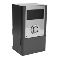
Button layout
The figure below shows buttons used to operate the digital
thermostats.
Item Description
A The - and + buttons are used to:
• Adjust setpoint temperature
• Modify settings menu parameters
B
C The OK button is used to:
• Toggle between current status data, and values of available
sensors connected to the thermostat
• Enter and exit the settings menu
• Confirm a setting
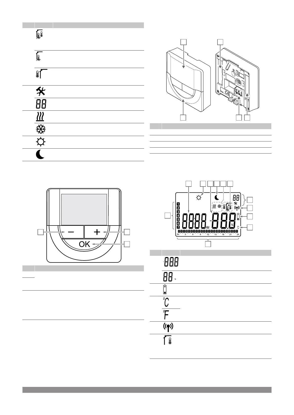
Uponor Smatrix Wave T-168
The illustration below shows the parts of the thermostat.
Item Description
A Display
B Buttons
C Terminal for external sensor (non-polarised)
D Batteries
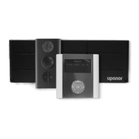
Display layout
The figure shows all possible symbols and characters that can be
shown on the display:
Item Icon Description
A Temperature reading using a - or + sign, two digital
characters, a decimal point and a character showing
either 0 or 5
Relative humidity reading using two digital characters.
Indicated with a “%” character
B Low battery indicator
C Temperature unit, shown when the character group A
shows a temperature
D Communication indicator
E Indoor temperature indicator
Remote sensor temperature indicator (RS mode)
The text Err and a flashing sensor icon indicates a
faulty sensor
Uponor Smatrix Wave PULSE
|
Installation and operation manual
|
83