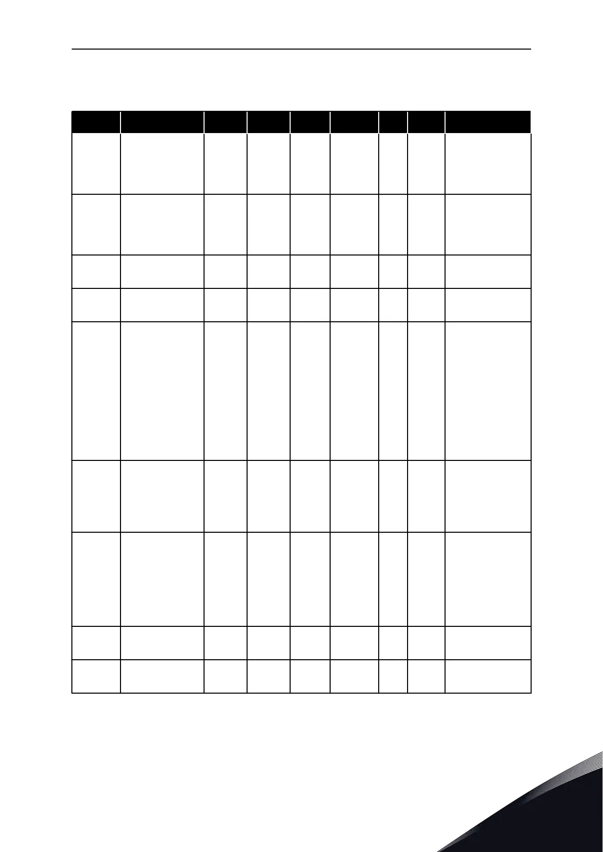
5.4.5 DRIVE CONTROL PARAMETERS (CONTROL KEYPAD: MENU M2 -> G2.4
Table 38: Drive control parameters, G2.4
Index Parameter Min Max Unit Default Cust ID Description
P2.4.1 Ramp 1 shape 0.0 10.0 s 0.1 500
0 = Linear
>0 = S-curve ramp
time
P2.4.2 Ramp 2 shape 0.0 10.0 s 0.0 501
0 = Linear
>0 = S-curve ramp
time
P2.4.3
Acceleration time
2
0.1 3000.0 s 1.0 502
P2.4.4
Deceleration time
2
0.1 3000.0 s 1.0 503
P2.4.5 Brake chopper 0 4 0 504
0 = Disabled
1 = Used when
running
2 = External brake
chopper
3 = Used when
stopped/running
4 = used when
running (no test-
ing)
P2.4.6 Start function 0 2 0 505
0 = Ramp
1 = Flying start
2 = Conditional fly-
ing start
P2.4.7 Stop function 0 3 0 506
0 = Coasting
1 = Ramp
2 = Ramp+Run
enable coast
3 = Coast+Run
enable ramp
P2.4.8
DC braking cur-
rent
0.00 I
L
A 0.7 x I
H
507
P2.4.9
DC braking time
at stop
0.00 600.00 s 0.00 508
0 = DC brake is off
at stop
PID CONTROL APPLICATION VACON · 115
24-HOUR SUPPORT +358 (0)201 212 575 · EMAIL: VACON@VACON.COM
5
 Loading...


