8.2 MASTER/FOLLOWER FUNCTION (NXP ONLY)
The Master/Follower function is designed for applications in which the system is run by
several NXP drives and the motor shafts are coupled to each other via gearing, chain, belt
etc. It is recommended that the Closed Loop control mode be used.
The external Start/Stop control signals are connected to the Master drive only. Speed and
torque references and control modes are selected for each drive separately. The Master
controls the Follower(s) via a SystemBus. The Master station is typically speed-controlled
and the other drives follow its torque or speed reference.
Torque control of the Follower should be used when the motor shafts of the Master and
Follower drives are solidly coupled to each other by gearing, a chain etc., so that no speed
difference between the drives is possible. Window control is recommended to keep the speed
of the follower close to that of the master.
Speed control of the Follower should be used when the demand of speed accuracy is lower.
In such cases, use of load drooping is recommended in all drives to balance the load.
8.2.1 MASTER/FOLLOWER LINK PHYSICAL CONNECTIONS
In figures below, the master drive is located on the left side and all others are followers. The
master/follower physical link can be built with OPTD2 option board. See Vacon NX I/O Board
Manual for further information.
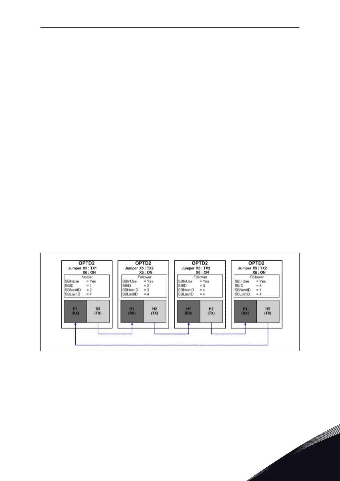
8.2.2 OPTICAL FIBRE CONNECTION BETWEEN AC DRIVES WITH OPTD2
The OPTD2 board in the Master has the default jumper selections, i.e. X6:1-2, X5:1-2. For the
followers, the jumper positions have to be changed: X6:1-2, X5:2-3. This board also has a
CAN communication option that is useful for multiple drive monitoring with NCDrive PC
software, when commissioning Master Follower functions or line systems.
Fig. 91: System bus physical connections with the OPTD2 board
For information on the OPTD2 expander board parameters, see Vacon NX I/O Board Manual.
PARAMETER DESCRIPTIONS VACON · 367
24-HOUR SUPPORT +358 (0)201 212 575 · EMAIL: VACON@VACON.COM
8

 Loading...


