EasyManuals Logo

Vacon NX series Applications Manual

Vacon NX series
392 pages
To Next Page IconTo Next Page
To Previous Page IconTo Previous Page
Page #214 background imageLoading...
Page #214 background image
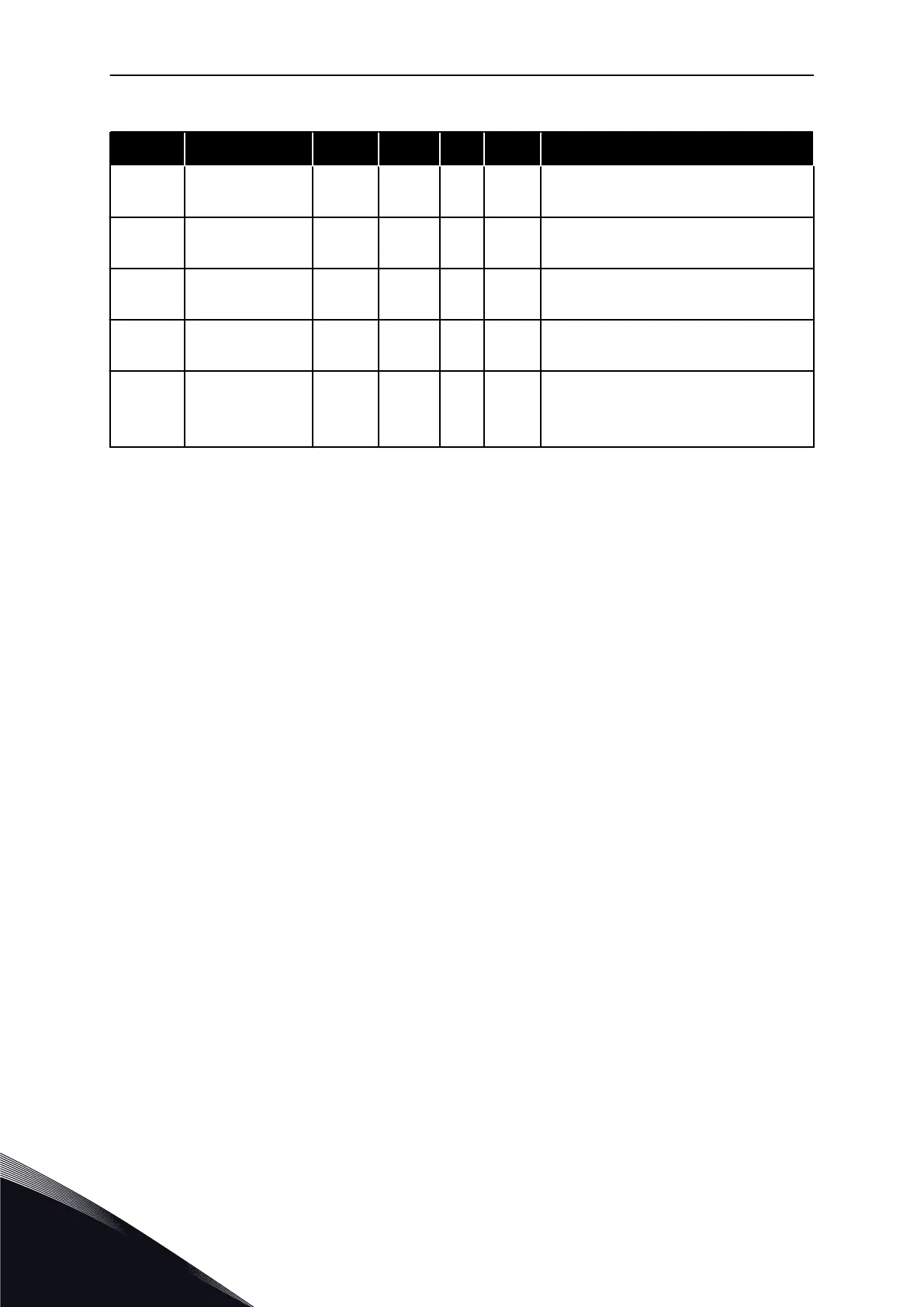
Table 91: Digital inputs (Control keypad: Menu M2 -> G2.2.4)
Index Parameter Min Default Cust ID Description
P2.2.6.19
*
Autochange 2
Interlock
0.1 A.3 427
Activated if cc
P2.2.6.20
*
Autochange 3
Interlock
0.1 0.1 428
Activated if cc
P2.2.6.21
*
Autochange 4
Interlock
0.1 0.1 429
Activated if cc
P2.2.6.22
*
Autochange 5
Interlock
0.1 0.1 430
Activated if cc
P2.2.6.23
*
PID reference 2 0.1 0.1 431
Selected with P2.1.11 (oc)
Selected with P2.2.1.4 (cc)
cc = closing contact
oc = opening contact
* Apply the Terminal to Function method (TTF) to these parameters (see chapter 8.9
"Terminal to function" (TTF) programming principle).
7.4.4 OUTPUT SIGNALS
Use TTF method to program for all Digital output signal parameters.
VACON · 214 PUMP AND FAN CONTROL APPLICATION
7
TEL. +358 (0)201 2121 · FAX +358 (0)201 212 205

Table of Contents

Other manuals for Vacon NX series

Questions and Answers:

Question and Answer IconNeed help?

Do you have a question about the Vacon NX series and is the answer not in the manual?

Vacon NX series Specifications

General IconGeneral
Product typeAC Drive
Output voltage range0-Uin
Frequency range0-500 Hz
Enclosure classesIP00, IP21
Mounting typesWall
Braking chopperIntegrated or external
EMC filterBuilt-in or external
Control modesScalar, Vector
Protection featuresOvercurrent, overvoltage, undervoltage, overtemperature, short circuit
Communication optionsModbus, Profibus, CANopen, Ethernet
Ambient temperature range-10°C to +50°C
Cooling methodAir-cooled

Related product manuals