6.4.5 DRIVE CONTROL PARAMETERS (CONTROL KEYPAD: MENU M2 -> G2.4
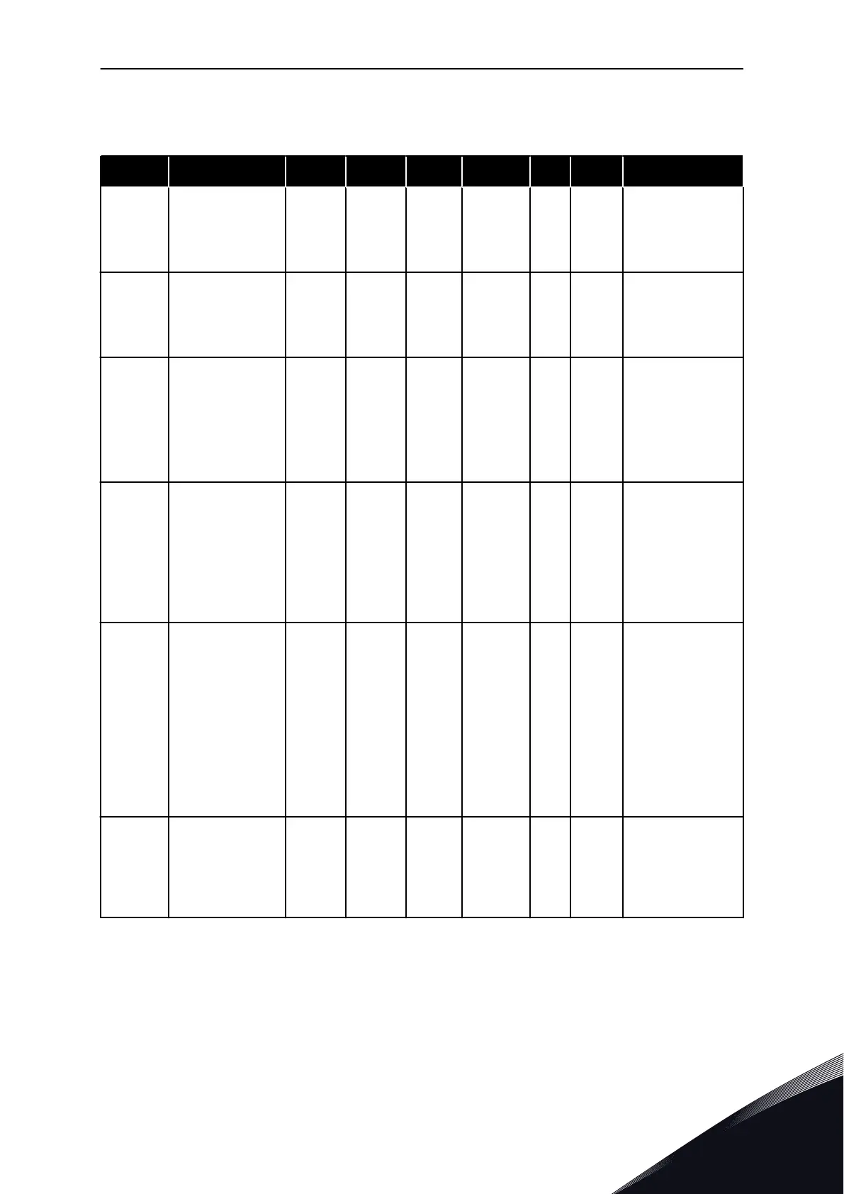
Table 69: Drive control parameters, G2.4
Index Parameter Min Max Unit Default Cust ID Description
P2.4.1 Ramp 1 shape 0.0 10.0 s 0.1 500
0 = Linear
100 = Full acc/dec
inc/dec times
P2.4.2 Ramp 2 shape 0.0 10.0 s 0.0 501
0 = Linear
100 = Full acc/dec
inc/dec times
P2.4.3
Acceleration time
2
0.1 3000.0 s 10.0 502
Defines the time
that is necessary
for the output fre-
quency to increase
from zero fre-
quency to maxi-
mum frequency.
P2.4.4
Deceleration time
2
0.1 3000.0 s 10.0 503
Defines the time
that is necessary
for the output fre-
quency to
decrease from
maximum fre-
quency to zero fre-
quency.
P2.4.5 * Brake chopper 0 4 0 504
0 = Disabled
1 = Used when
running
2 = External brake
chopper
3 = Used when
stopped/running
4 = used when
running (no test-
ing)
P2.4.6 Start function 0 2 0 505
0 = Ramp
1 = Flying start
2 = Conditional fly-
ing start
MULTI-PURPOSE CONTROL APPLICATION VACON · 165
24-HOUR SUPPORT +358 (0)201 212 575 · EMAIL: VACON@VACON.COM
6
 Loading...


