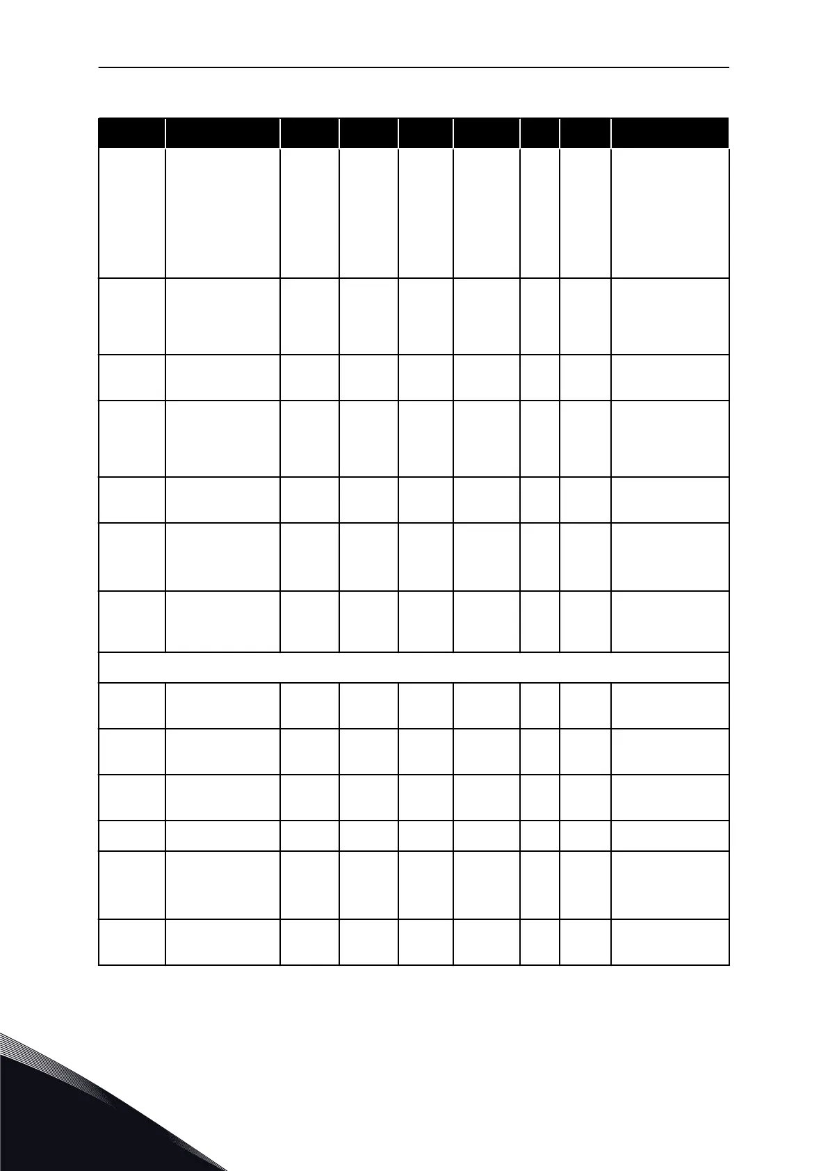
Table 69: Drive control parameters, G2.4
Index Parameter Min Max Unit Default Cust ID Description
P2.4.7 Stop function 0 3 0 506
0 = Coasting
1 = Ramp
2 = Ramp+Run
enable coast
3 = Coast+Run
enable ramp
P2.4.8
DC braking cur-
rent
0.00 I
L
A 0.7 x I
H
507
Defines the cur-
rent injected into
the motor during
DC braking.
P2.4.9
DC braking time
at stop
0.00 600.00 s 0.00 508
0 = DC brake is off
at stop
P2.4.10
Frequency to start
DC braking during
ramp stop
0.10 10.00 Hz 1.50 515
The output fre-
quency at which
the DCbraking is
applied.
P2.4.11
DC braking time
at start
0.00 600.00 s 0.00 516
0 = DC brake is off
at start
P2.4.12 Flux brake 0 1 0 520
0 = Off
0 = On
P2.4.13
Flux braking cur-
rent
0.00 I
L
A I
H
519
Gives the current
level for the flux
braking.
NXP drives only
P2.4.14
DC-brake current
at stop
0 I
L
A 0.1 x I
H
1080
P2.4.15
Inching reference
1
-320.00 320.00 Hz 2.00 1239
P2.4.16
Inching reference
2
-320.00 320.00 Hz 653.36 1240
P2.4.17 Inching ramp 0.1 3200.0 s 1.0 1257
P2.4.18
Emergency stop
mode
0 1 0 1276
0 = Coasting
1 = Ramp
P2.4.19 Control options 0 65536 0 1084
Change allowed
only in Stop state.
VACON · 166 MULTI-PURPOSE CONTROL APPLICATION
6
TEL. +358 (0)201 2121 · FAX +358 (0)201 212 205
 Loading...


