•
If the number of running auxiliary drives is smaller than the value of parameter 2.9.27
the autochange function can take place.
•
If the number of running auxiliary drives is equal to the value of parameter 2.9.27 and the
frequency of the controlled drive is below the value of parameter 2.9.28 the autochange
can take place.
•
If the value of parameter 2.9.28 is 0.0 Hz, the autochange can take place only in rest
position (Stop and Sleep) regardless of the value of parameter 2.9.27.
8.12 INTERLOCK SELECTION (P2.9.23)
This parameter is used to activate the interlock inputs. The interlocking signals come from
the motor switches. The signals (functions) are connected to digital inputs which are
programmed as interlock inputs using the corresponding parameters. The pump and fan
control automatics only control the motors with active interlock data.
•
The interlock data can be used even when the Autochange function is not activated
•
If the interlock of an auxiliary drive is inactivated and another unused auxiliary drive
available, the latter will be put to use without stopping the AC drive.
•
If the interlock of the controlled drive is inactivated, all motors will be stopped and
restarted with the new set-up.
•
If the interlock is re-activated in Run status, the automatics functions according to
parameter 2.9.23, Interlock selection:
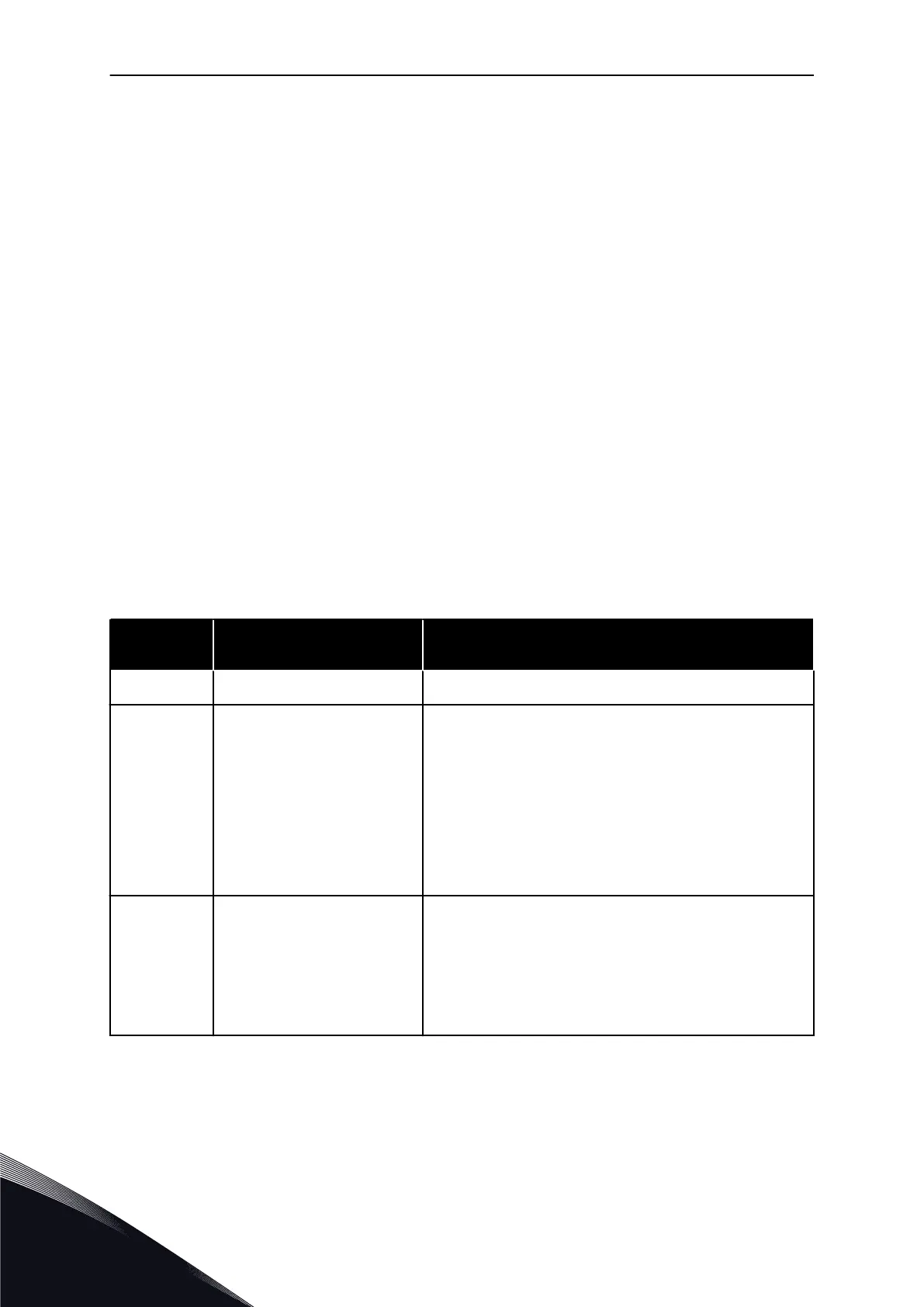
Table 217: Selections for Interlock selection
Selection
number
Selection name Description
0 Not used
1
Update in stop Interlocks are used. The new drive will be placed last in the
autochange line without stopping the system. However, if the
autochange order now becomes, for example, [P1 -> P3 ->
P4 -> P2], it will be updated in the next Stop (autochange,
sleep, stop, etc.).
EXAMPLE:
[P1 -> P3 -> P4] -> [P2 LOCKED] ->[P1 -> P3 -> P4 -> P2] ->
[SLEEP] -> [P1 -> P2 -> P3 -> P4]
2
Stop & Update Interlockings are used. The automatics will stop all motors
immediately and re-start with a new set-up.
EXAMPLE:
[P1 -> P2 -> P4] -> [P3 LOCKED] -> [STOP] -> [P1 -> P2 -> P3
-> P4]
See Chapter 8.13 Examples of Autochange and Interlock selection.
VACON · 380 PARAMETER DESCRIPTIONS
8
TEL. +358 (0)201 2121 · FAX +358 (0)201 212 205
 Loading...


