1027 AUTOCHANGE 7 (2.9.24)
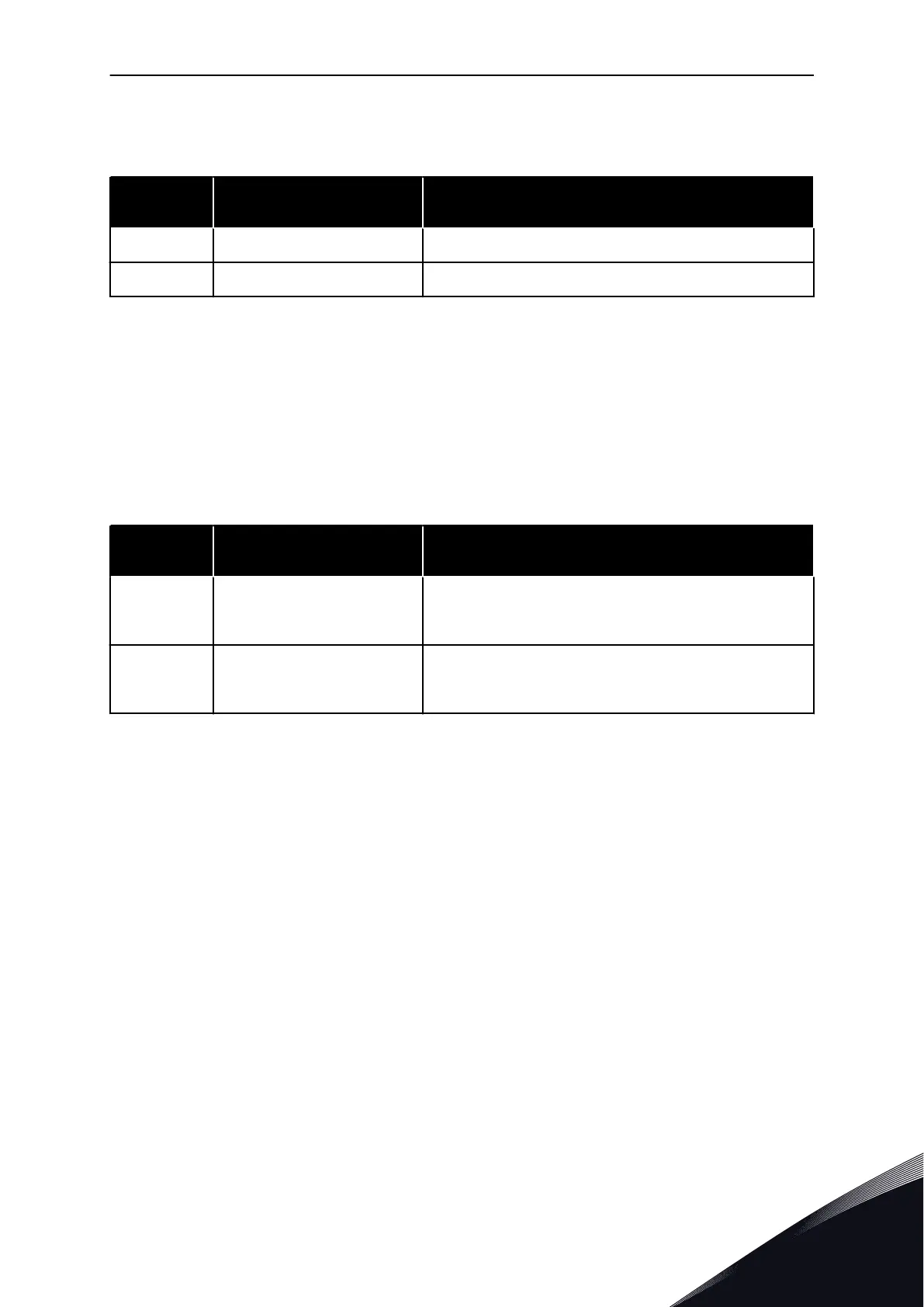
Table 215: Selections for parameter ID1027
Selection
number
Selection name Description
0 Autochange not used
1 Autochange used
The automatic change of starting and stopping order is activated and applied to either the
auxiliary drives only or the auxiliary drives and the drive controlled by the AC drive.
depending on the setting of parameter 2.9.25, Automatics selection. By default, the
Autochange is activated for 2 drives. See Fig. 19 Pump and fan control application default I/O
configuration andconnection example (with 2-wire transmitter) and Fig. 98 Example of 2-pump
autochange, main diagram.
1028 AUTOCHANGE/INTERLOCKINGS AUTOMATICS SELECTION 7 (2.9.25)
Table 216: Selections for parameter ID1028
Selection
number
Selection name Description
0
Automatics (autochange/inter-
lockings) applied to auxiliary
drives only
The drive controlled by the AC drive remains the same.
Therefore, mains contactor is needed for one auxiliary drive
only.
1
All drives included in the
autochange/interlockings
sequence
The drive controlled by the AC drive is included in the auto-
matics and a contactor is needed for each drive to connect it
to either the mains or the AC drive.
1029 AUTOCHANGE INTERVAL 7 (2.9.26)
After the expiry of the time defined with this parameter, the autochange function takes place
if the capacity used lies below the level defined with parameters 2.9.28 (Autochange
frequency limit) and 2.9.27 (Maximum number of auxiliary drives). Should the capacity exceed
the value of P2.9.28, the autochange will not take place before the capacity goes below this
limit.
•
The time count is activated only if the Start/Stop request is active at control place A.
•
The time count is reset after the autochange has taken place or on removal of Start
request at control place A.
1030 AND 1031 MAXIMUM NUMBER OF AUXILIARY DRIVES AND AUTOCHANGE FREQUENCY
LIMIT (2.9.27 AND 2.9.28)
These parameters define the level below which the capacity used must remain so that the
autochange can take place.
This level is defined as follows:
PARAMETER DESCRIPTIONS VACON · 379
24-HOUR SUPPORT +358 (0)201 212 575 · EMAIL: VACON@VACON.COM
8
 Loading...


