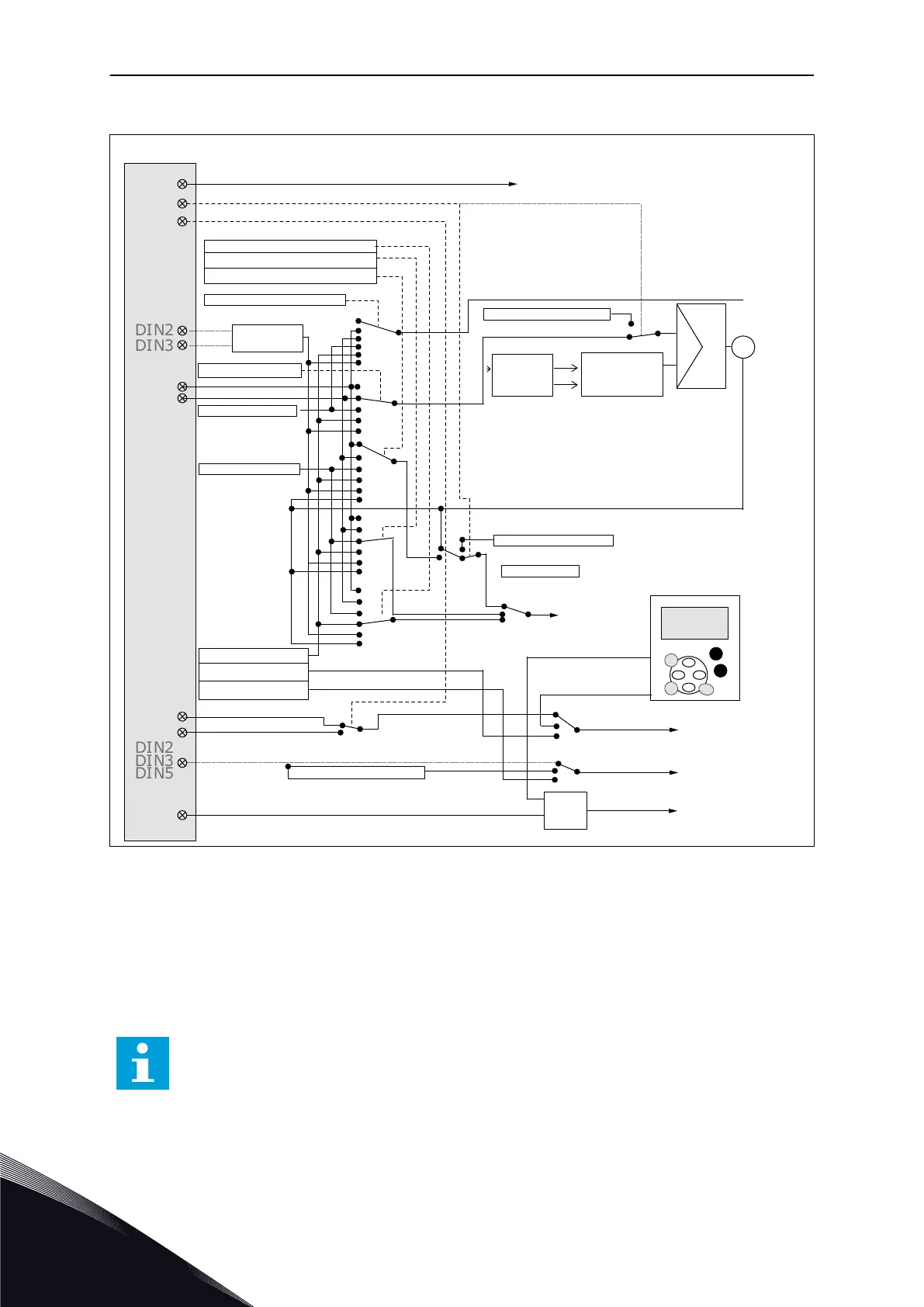
5.3 CONTROL SIGNAL LOGIC IN PID CONTROL APPLICATION
DIN2
DIN5
DIN3
DIN2
DIN3
DIN5
DIN6
DIN2
DIN3
AI1
AI2
0
1
2
3
4
0
1
2
3
4
5
+A
A
B
0
1
2
3
4
5
0
1
2
3
4
5
K
0
1
2
3
4
5
F
PID
+
DIN1
DIN4
A
B
A
B
A/B
Internal reverse
Internal fault reset
Fault reset input (programmable)
3.3 Keypad direction
Internal Start/Stop
Reference from fieldbus
Start/Stop from fieldbus
Direction from fieldbus
External fault (programmable)
Jogging speed (programmable)
Place A/B selection
2.2.4 PID main reference
Up
Down
2.1.11 PID reference
I/O reverse
R3.4 PID keypad refer.
R3.2 Keypad refer.
Act 1
Act 2
R3.5 PID keypad ref. 2
Enable PID keypad
ref. 2 (DIN5=13)
Start; Place A
Start; Place B
Start/Stop
Start/Stop buttons
Internal
frequency ref.
2.1.19 Jogging speed ref.
Keypad
Fieldbus
Reset button
3.1 Control place
2.2.7 Fieldbus Ctrl Reference
2.2.6 Keypad Crtl Reference
2.2.5 I/O B Reference
≥ 1
Motor
potentiometer
Actual value
sselection,
par.2.2.9 &
2.2.10
Actual value
selection par.
2.2.8
Fig. 15: Control signal logic of the PID Control Application
5.4 PID CONTROL APPLICATION - PARAMETER LISTS
5.4.1 MONITORING VALUES (CONTROL KEYPAD: MENU M1)
The monitoring values are the actual values of parameters and signals as well as statuses
and measurements. Monitoring values cannot be edited.
NOTE!
The monitoring values V1.19 to V1.22 are available with the PID control application
only.
VACON · 98 PID CONTROL APPLICATION
5
TEL. +358 (0)201 2121 · FAX +358 (0)201 212 205
 Loading...


