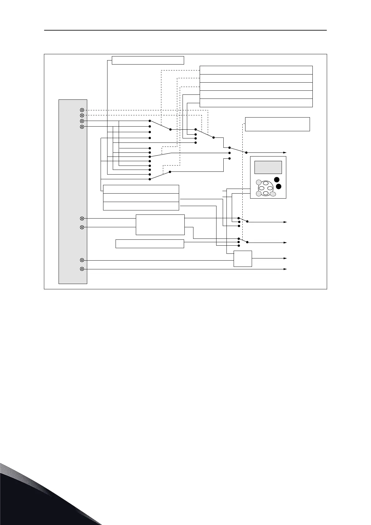
2.3 CONTROL SIGNAL LOGIC IN STANDARD APPLICATION
DIN4
DIN5
AI1
AI2
DIN1
DIN2
DIN6
DIN3
≥ 1
3.2 Keypad reference
3.1 Control place
Start forward
Start reverse
Start/Stop
Reverse
Internal Start/Stop
Internal reverse
Internal fault reset
Fault reset input
External fault input (programmable)
Reset button
Start/Stop buttons
Reference from fieldbus
Start/Stop from fieldbus
Direction from fieldbus
3.3 Keypad direction
2.1.13 Fieldbus Ctrl Reference
2.1.15 Preset Speed 2
2.1.14 Preset Speed 1
2.1.11 I/O Reference
2..1.12 Keypad Ctrl Speed 1
Programmable
Start/Stop and
reverse logic
Internal frequency
reference
(programmable)
(programmable)
Fig. 6: Control signal logic of the Standard Application
2.4 STANDARD APPLICATION - PARAMETER LISTS
2.4.1 MONITORING VALUES (CONTROL KEYPAD: MENU M1)
The monitoring values are the actual values of parameters and signals as well as statuses
and measurements. Monitoring values cannot be edited.
VACON · 22 STANDARD APPLICATION
2
TEL. +358 (0)201 2121 · FAX +358 (0)201 212 205

 Loading...


