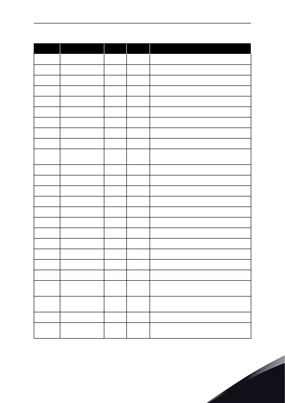
Table 84: Monitoring values
Index Monitoring value Unit ID Description
V1.1 Output frequency Hz 1 The output frequency to motor
V1.2 Frequency reference Hz 25 The frequency reference to motor control
V1.3 Motor speed rpm 2 The actual speed of the motor in rpm
V1.4 Motor current A 3
V1.5 Motor torque % 4 The calculated shaft torque
V1.6 Motor power % 5 The calculated motor shaft power in percentage
V1.7 Motor voltage V 6 The output voltage to motor
V1.8 DC link voltage V 7 The measured voltage in the DC-link of the drive
1.9 Unit temperature °C 8 The heatsink temperature in Celsius or Fahrenheit
1.10 Motor temperature % 9
The calculated motor temperature in percentage
of the nominal working temperature
V1.11 Analogue input 1 V/mA 13 AI1
V1.12 Analogue input 2 V/mA 14 AI2
V1.13 DIN 1, 2, 3 15 Shows the status of the digital inputs 1-3
V1.14 DIN 4, 5, 6 16 Shows the status of the digital inputs 4-6
V1.15 Analogue I
out
mA 26 AO1
V1.16 Analogue input 3 V/mA 27 AI3 input value
V1.17 Analogue input 4 V/mA 28 AI4 input value
V1.18 PID Reference % 20 In % of the max. frequency
V1.19 PID Actual value % 21 In % of the max actual value
V1.20 PID Error value % 22 In % of the max error value
V1.21 PID Output % 23 In % of the max output value
V1.22
Running auxiliary
drives
30
Number of running auxiliary drives
V1.23
Special display for
actual value
29
See parameters 2.9.29 to 2.9.31
V1.24 PT-100 temperature ºC 42 Highest temperature of used PT100 inputs
G1.25
Multimonitoring
items
Displays three selectable monitoring values
PUMP AND FAN CONTROL APPLICATION VACON · 201
24-HOUR SUPPORT +358 (0)201 212 575 · EMAIL: VACON@VACON.COM
7
 Loading...


