EasyManuals Logo

Vacon NX series Applications Manual

Vacon NX series
392 pages
To Next Page IconTo Next Page
To Previous Page IconTo Previous Page
Page #232 background imageLoading...
Page #232 background image
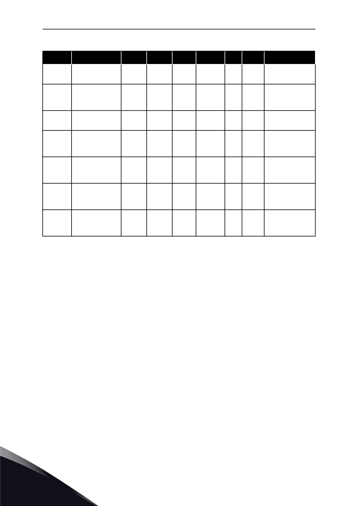
Table 102: Pump and fan control parameters
Index Parameter Min Max Unit Default Cust ID Description
P2.9.26
Autochange inter-
val
0.0 3000.0 h 48.0 1029
0.0 = TEST=40 s
P2.9.27
Autochange; Max-
imum number of
auxiliary drives
0 4 1 1030
P2.9.28
Autochange fre-
quency limit
0.00 P2.1.2 Hz 25.00 1031
P2.9.29
Actual value spe-
cial display mini-
mum
0 30000 0 1033
P2.9.30
Actual value spe-
cial display maxi-
mum
0 30000 100 1034
P2.9.31
Actual value spe-
cial display deci-
mals
0 4 1 1035
P2.9.32
Actual value spe-
cial display unit
0 28 4 1036
See ID1036 in
Chapter 8 Parame-
ter descriptions.
7.4.11 KEYPAD CONTROL (CONTROL KEYPAD: MENU M3)
The parameters for the selection of control place and direction on the keypad are listed
below. See the Keypad control menu in the product's User Manual.
VACON · 232 PUMP AND FAN CONTROL APPLICATION
7
TEL. +358 (0)201 2121 · FAX +358 (0)201 212 205

Table of Contents

Other manuals for Vacon NX series

Questions and Answers:

Question and Answer IconNeed help?

Do you have a question about the Vacon NX series and is the answer not in the manual?

Vacon NX series Specifications

General IconGeneral
Product typeAC Drive
Output voltage range0-Uin
Frequency range0-500 Hz
Enclosure classesIP00, IP21
Mounting typesWall
Braking chopperIntegrated or external
EMC filterBuilt-in or external
Control modesScalar, Vector
Protection featuresOvercurrent, overvoltage, undervoltage, overtemperature, short circuit
Communication optionsModbus, Profibus, CANopen, Ethernet
Ambient temperature range-10°C to +50°C
Cooling methodAir-cooled

Related product manuals