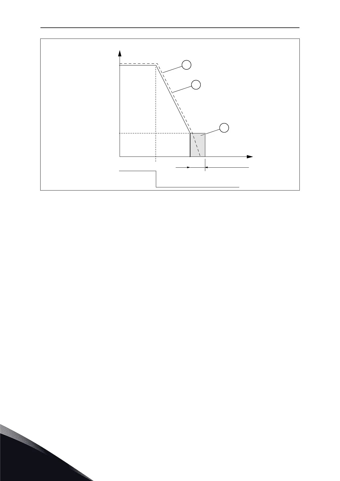
EasyManuals Logo

Vacon NX series Applications Manual

Vacon NX series
392 pages
To Next Page IconTo Next Page
To Previous Page IconTo Previous Page
Page #306 background imageLoading...
Page #306 background image
A
B
C
t = Par. ID508
t
par. ID515
RUN
STOP
f
out
Fig. 69: DC-braking time when Stop mode = Ramp
A. Motor speed
B. Output frequency
C. DC-braking
509 PROHIBIT FREQUENCY AREA 1; LOW LIMIT 23457 (2.5.1)
510 PROHIBIT FREQUENCY AREA 1; HIGH LIMIT 23457 (2.5.2)
511 PROHIBIT FREQUENCY AREA 2; LOW LIMIT 3457 (2.5.3)
512 PROHIBIT FREQUENCY AREA 2; HIGH LIMIT 3457 (2.5.4)
513 PROHIBIT FREQUENCY AREA 3; LOW LIMIT 3457 (2.5.5)
514 PROHIBIT FREQUENCY AREA 3; HIGH LIMIT 3457 (2.5.6)
In some systems it may be necessary to avoid certain frequencies because of mechanical
resonance problems. With these parameters it is possible to set limits for the "skip
frequency" region.
VACON · 306 PARAMETER DESCRIPTIONS
8
TEL. +358 (0)201 2121 · FAX +358 (0)201 212 205

Table of Contents

Other manuals for Vacon NX series

Questions and Answers:

Question and Answer IconNeed help?

Do you have a question about the Vacon NX series and is the answer not in the manual?

Vacon NX series Specifications

General IconGeneral
Product typeAC Drive
Output voltage range0-Uin
Frequency range0-500 Hz
Enclosure classesIP00, IP21
Mounting typesWall
Braking chopperIntegrated or external
EMC filterBuilt-in or external
Control modesScalar, Vector
Protection featuresOvercurrent, overvoltage, undervoltage, overtemperature, short circuit
Communication optionsModbus, Profibus, CANopen, Ethernet
Ambient temperature range-10°C to +50°C
Cooling methodAir-cooled

Related product manuals