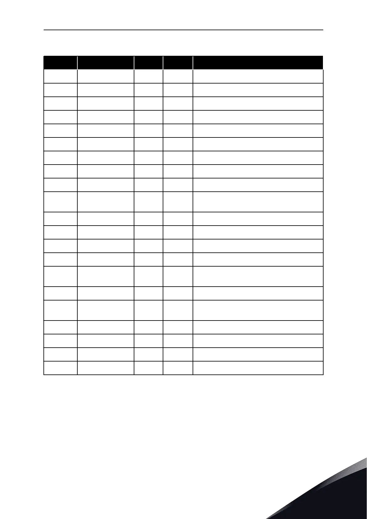
Table 24: Monitoring values
Index Monitoring value Unit ID Description
V1.1 Output frequency Hz 1 The output frequency to motor
V1.2 Frequency reference Hz 25 The frequency reference to motor control
V1.3 Motor speed rpm 2 The actual speed of the motor in rpm
V1.4 Motor current A 3
V1.5 Motor torque % 4 The calculated shaft torque
V1.6 Motor power % 5 The calculated motor shaft power in percentage
V1.7 Motor voltage V 6 The output voltage to motor
V1.8 DC link voltage V 7 The measured voltage in the DC-link of the drive
1.9 Unit temperature °C 8 The heatsink temperature in Celsius or Fahrenheit
1.10 Motor temperature % 9
The calculated motor temperature in percentage
of the nominal working temperature
V1.11 Analogue input 1 V/mA 13 AI1
V1.12 Analogue input 2 V/mA 14 AI2
V1.13 DIN 1, 2, 3 15 Shows the status of the digital inputs 1-3
V1.14 DIN 4, 5, 6 16 Shows the status of the digital inputs 4-6
V1.15 DO1, RO1, RO2 17
Shows the status of the digital and relay outputs
1-3
V1.16 Analogue I
out
mA 26 AO1
V1.17
Multimonitoring
items
Displays three selectable monitoring values
V1.18.1 Current A 1113
V1.18.2 Torque % 1125
V1.18.3 DC Voltage V 44
V1.18.4 Status Word 43
MULTI-STEP SPEED CONTROL APPLICATION VACON · 73
24-HOUR SUPPORT +358 (0)201 212 575 · EMAIL: VACON@VACON.COM
4
 Loading...


