When configuring the non-display transmitter, the Ethernet connector can be
used without taking the cable through the cable gland. Always wire through the
cable gland for more long-term wiring.
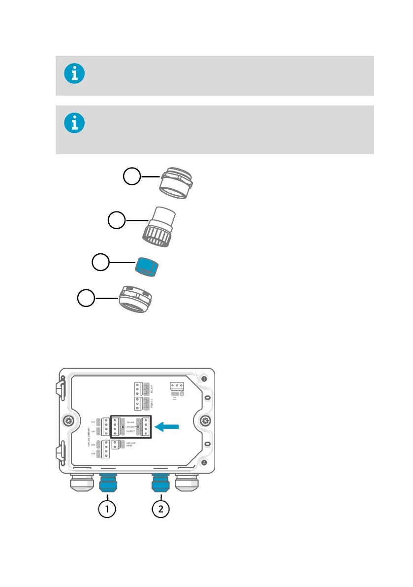
When you insert the cable through the gland parts, also remove the split bushing
(3) inside the nylon seal (2) to make the cable fit through the seal. Then place the
bushing around the cable and push it back inside the seal. See the following
figure.
Figure 15 M20×1.5 cable gland with split
bushing
1 Base of the cable gland
2 Nylon seal
3 Split bushing inside the seal
4 Nut of the cable gland
3.3.7 Probe connection terminals and lead-throughs
Before connecting wires or cables, make sure that the transmitter is powered o.
For the M16×1.5 cable glands ordered
together with the transmitter from Vaisala,
the cable diameter is 2.0 … 6.0 mm
(0.08 … 0.24 in). Tightening torque for the
cable gland is 6 Nm.
The minimum length of the probe
connection cable is 30 cm (11.81 in). The
recommended maximum length of the
probe connection cable is 30 m (98 ft).
1 Probe 1 lead-through, M16×1.5
2 Probe 2 lead-through, M16×1.5
Chapter 3 – Installation
43

 Loading...


