Chapter 4 _________________________ Installation of the Weather Station Components to the Mast
VAISALA ______________________________________________________________________ 121
0310-046
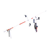
Figure 107 Installing a Radio Modem to Sensor Arm
1. Connect the data/power cable (number 3 in Figure 108 below) to
the radio modem (2), and lead the cable through the opening (1)
in the radiation shield.
2. Connect the other end of the cable to the PC Connector at the
bottom flange of the logger tube. For the location of the
connector, see Figure 95 on page 107.
0310-047
Figure 108 Connecting the Data/Power Cable between a
Radio Modem and Logger Tube
3. Connect the antenna cable (number 1 in Figure 109 on page
122) to the BNC connector (2) on a radio modem (3).

 Loading...