Installation Manual _________________________________________________________________
68 __________________________________________________________________ M210485EN-B
0303-038
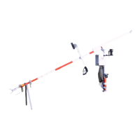
Figure 54 Dimensions (in mm) for Lightning Rod
Assembly on the Mast
NOTE
The transformation for the dimensions in Figure 54 above:
20 mm ≈ 0.79 in.
150 mm ≈ 5.91 in.
350 mm ≈ 13.8 in.
440 mm ≈ 15.7 in.
1065 mm ≈ 41.9 in
Connecting the Grounding Cable to
the Insulated Guy Wire
Before erecting the mast, connect the grounding cable to the insulated
guy wire as follows:
1. Aim the insulated guy wire so that it points northwest (in the
northern hemisphere) when the mast is erected. The lightning
rod holders are aligned to the same direction as the insulated guy
wire, see Figure 55 on page 69.
2. Attach the grounding cable (number 3 in Figure 55 on page 69)
with a wire rope clip (5) below the insulator (4).
NOTE
Leave some extra cable between the lightning rod and the wire rope
clip on the guy wire to ensure that the guy wire does not pull the
lightning rod downwards.

 Loading...