The block diagram of the UPS module are shown in Figure 2.4 below, Figure 2.5 on the next page and Figure 2.6 on page13.
The UPS has split bypass configuration (the bypass adopts independent mains input) and common input configuration. In
split bypass configuration, the static bypass and maintenance bypass share the same independent bypass power supply.
Where a separate power source is not available, the input supply connections of the bypass input switch Q2 and rectifier input
switch Q1 would be linked together to make the bypass input and rectifier input use mains power of the same route.
During the normal operation of the UPS, except for the maintenance bypass switch Q3, other switches must be closed.
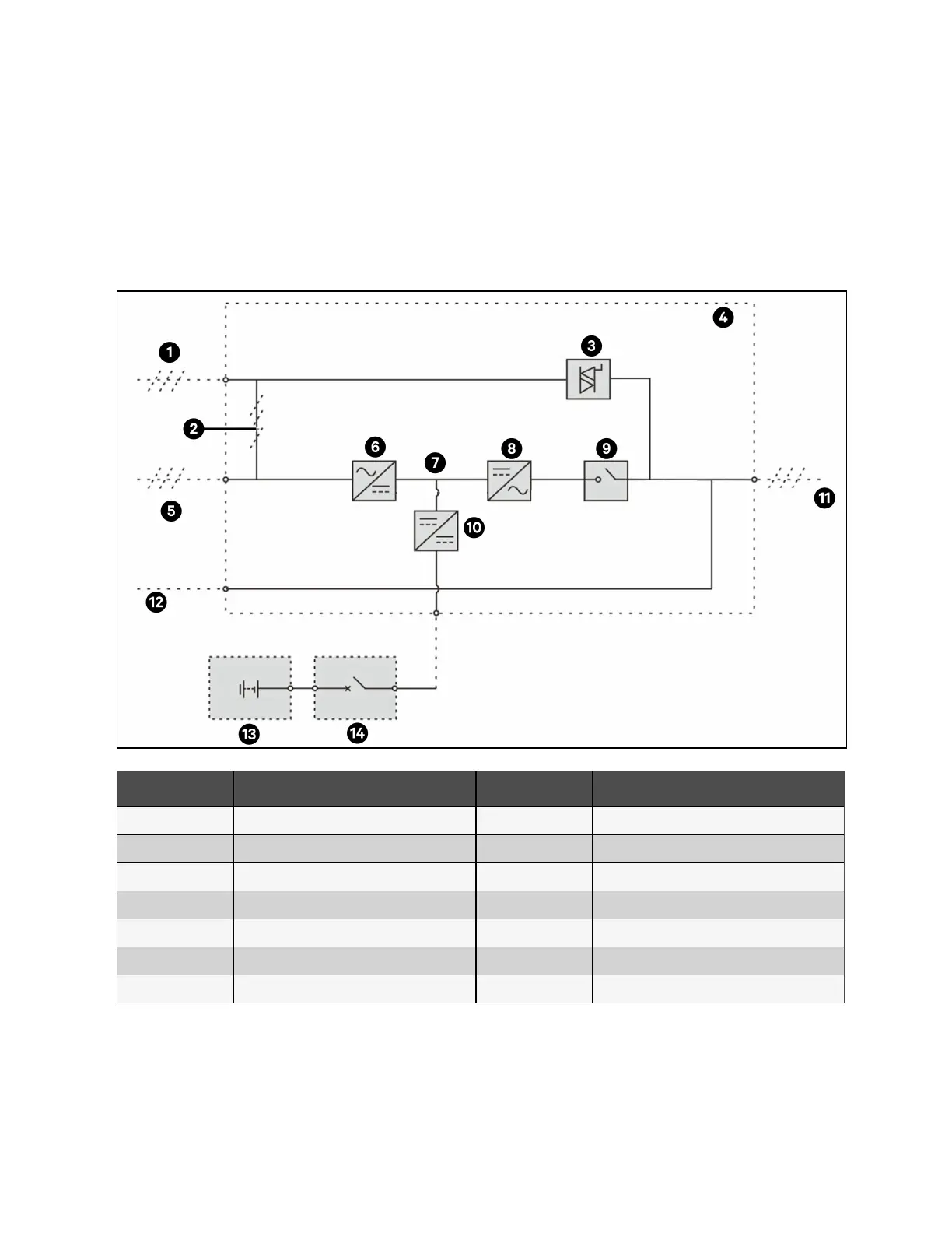
Figure 2.4 UPS Power Supply Switch Configuration Without Switch
Item Description Item Description
1 Bypass input 8 Inverter
2 Shorting copper bar of input configuration 9 Automatic Inverter switch
3 Static switch 10 Battery charger/discharger
4 UPS 11 UPS output
5 Mains input 12 Neutral line input
6 Rectifier 13 Battery
7 DC bus 14 BCB
2 Overview Proprietary and Confidential ©2023 Vertiv Group Corp. 11
Vertiv™ Liebert® APM2 30 to 120 kVA Modular UPS User Manual