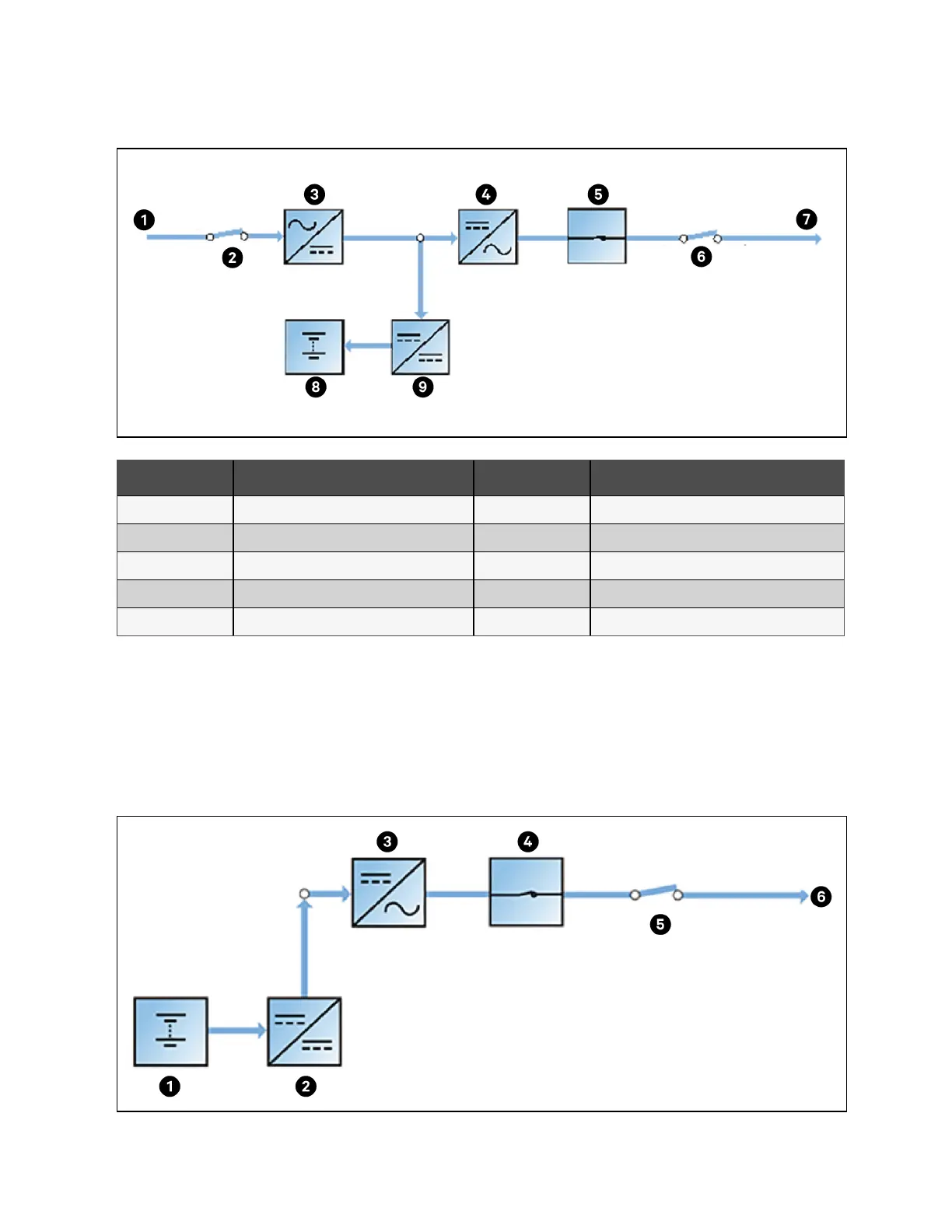
Figure 2.7 Schematic Diagram of Normal Mode
Item Description Item Description
1 Mains input 6 Output switch
2 Rectifier input switch 7 UPS output
3 Rectifier 8 Battery
4 Inverter 9 Battery charger/discharger
5 Automatic inverter switch
Battery mode
As shown in Figure 2.8 below, the operation mode in which the battery provides backup power supply to the loads through
the battery charger/discharger and inverter is called battery mode. Upon mains failure, the system will automatically transfer
to the battery mode with no load power interruption. When the mains is recovered, the system will automatically transfer back
to the normal mode without any manual intervention, and the power to the load will not be interrupted.
Figure 2.8 Schematic Diagram of Battery Mode
2 Overview Proprietary and Confidential ©2023 Vertiv Group Corp. 15
Vertiv™ Liebert® APM2 30 to 120 kVA Modular UPS User Manual