DV-1 SYSTEM OVERVIEW CONNECTIONS AND CABLE DIAGRAMS
19
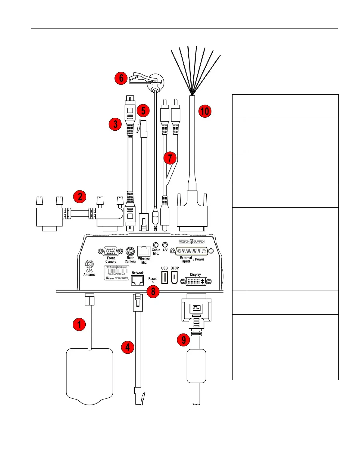
Figure 4 Connections and Cable Diagram – Modular Unit
Table 2 Modular Unit Cable
Descriptions
GPS Antenna: Connects the DV-1
to an optional GPS unit.
Front Camera Cable: Connects
the
DV-1 to the Front/Combination
Camera.
Rear/Auxiliary Camera Cable
(optional): Connects the DV-1 to
the Rear/Auxiliary Camera.
Network Cable: Connects the DV-
1 to a network.
Wireless Microphone Cable:
Connects the DV-1 to the wireless
microphone system.
Cabin Microphone Cable:
Captures audio from inside the
vehicle.
A/V: Connects audio/video
components to the DV-1.
Reset Button: Re-powers the
DV-1.
Display Cable: Connects the DV-1
to an external display.
External Inputs/Power Cable:
Provides power from the vehicle
battery to the DV-1 and provides
external trigger inputs such as
radar, siren, lights, etc.