MicroBlaze Processor Reference Guide 100
UG984 (v2018.2) June 21, 2018 www.xilinx.com
Chapter 2: MicroBlaze Architecture
The debug registers used to configure and control performance monitoring, and to read or
write the event and latency counters, are listed in
Table 2-42. All of these registers except
the Performance Counter Command register are accessed repeatedly to read or write
information, first for all of the event counters followed by all of the latency counters.
The DBG_CTRL value indicates the value to use in the MDM Debug Register Access Control
Register to access the register, used with MDM software access to debug registers.
Performance Counter Control Register
The Performance Counter Control Register (PCCTRLR) is used to define the events that are
counted by the configured performance counters. To define the events for all configured
counters, the register should be written repeatedly for each of the counters. This register is
a write-only register. Issuing a read request has no effect, and undefined data is read.
Every time the register is written, the selected counter is incremented. By using the
Performance Counter Command Register, the selected counter can be reset to the first
counter again. See the following figure and table.
Table 2-42: MicroBlaze Performance Monitoring Debug Registers
Register Name Size (bits)
MDM
Command
DBG_CTRL
Value
R/W Description
Performance
Counter Control
8
0101 0001 4A207 W
Select event for each configured
counter, according to
Table 2-41
Performance
Counter Command
5
0101 0010 4A404 W
Command to clear counters, start or
stop counting, or sample counters
Performance
Counter Status
2
0101 0011 4A601 R
Read the sampled status for each
configured performance counter
Performance
Counter Data Read
32
0101 0110 4AC1F R
Read the sampled values for each
configured performance counter
Performance
Counter Data Write
32
0101 0111 4AE1F W
Write initial values for each
configured performance counter
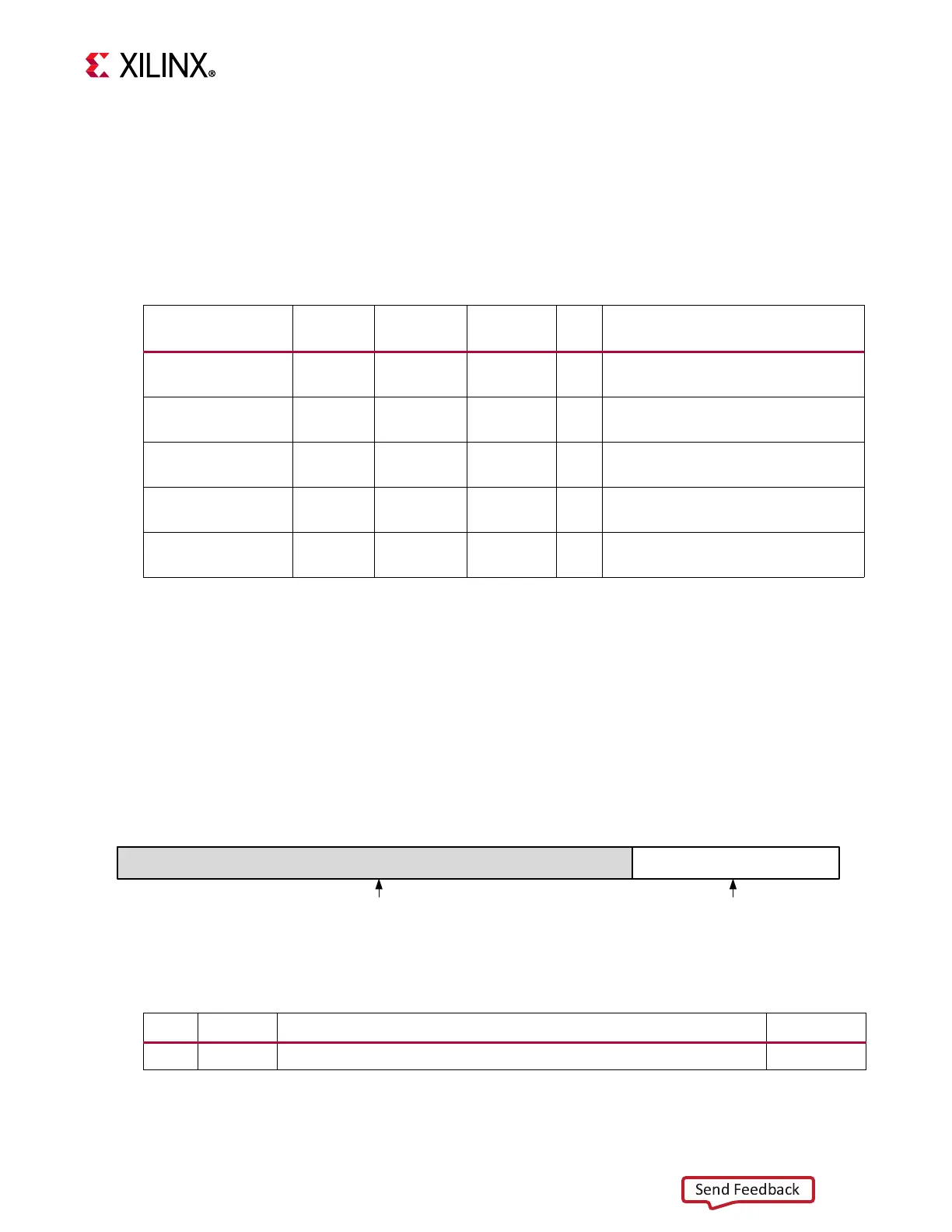
X-Ref Target - Figure 2-26
Figure 2-26: Performance Counter Control Register
0
7
Event
Reserved
31 8
X19762-082517
Table 2-43: Performance Counter Control Register (PCCTRLR)
Bits Name Description Reset Value
7:0 Event Performance counter event, according to Table 2-41.
0