8-18
–+
ELEC
E
ELECTRICAL ANALYSIS
50, 60, 70 hp
75, 80, 90 hp
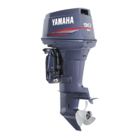
Charge coil
Output peak voltage (minimum)
Br – L
r/min
Cranking
1,500 3,500
Open Connect
V 120 150 160 120
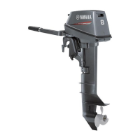
Charge coil
Output peak voltage (minimum)
R – Br
r/min
Cranking
1,500 3,500
Open Connect
V 55 60 170 150
Charge coil
Output peak voltage (minimum)
R – L
r/min
Cranking
1,500 3,500
Open Connect
V 90 100 135 135
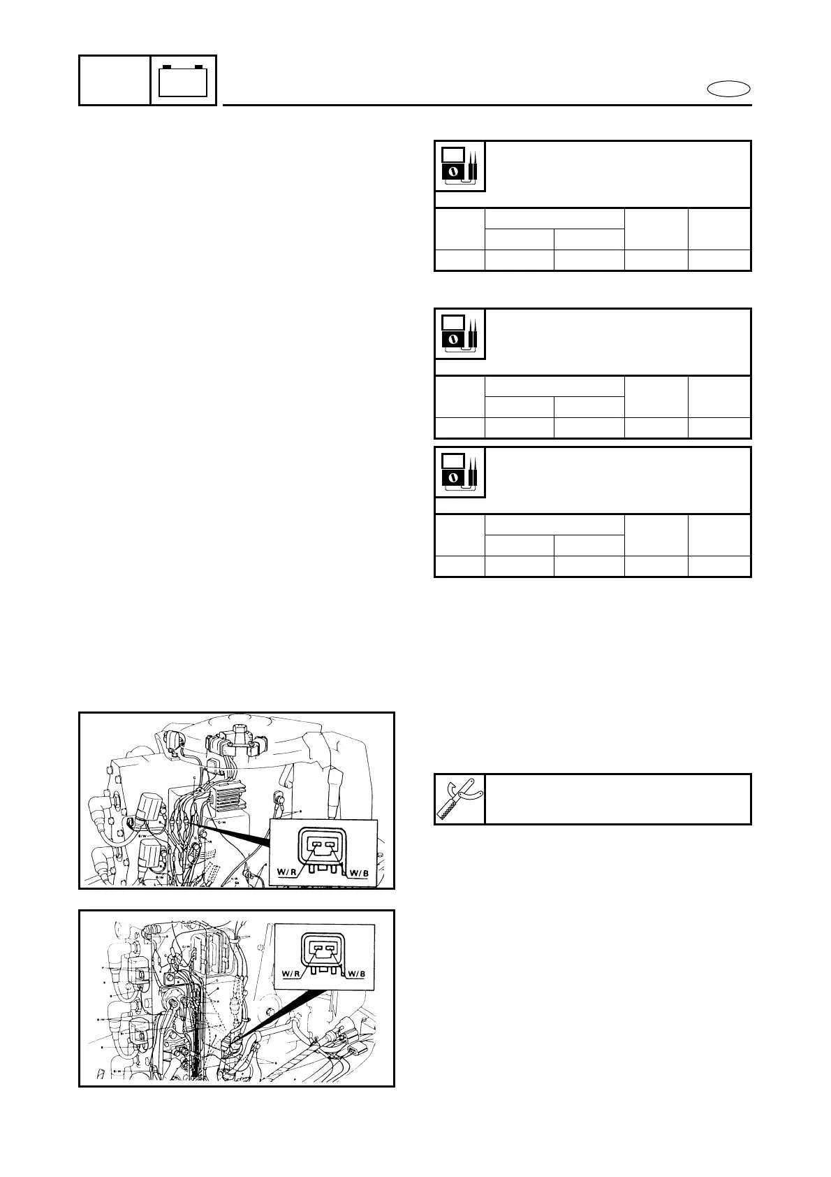
3. Pulser coil output:
1) Disconnect the pulse coil couple.
Connect the 2 pins test harness.
2) Connect the tester to the measure-
ment terminal.
3) Set the tester dial to specification.
4) Crank or start the engine.
5) Measure the pulser coil output.
6) If the output is beyond specification,
replace CDI unit.
7) If the output is below specification,
replace pulser coil.
2 pins test harness:
YB-38831/90890-06767
 Loading...