E
A50001-1-4
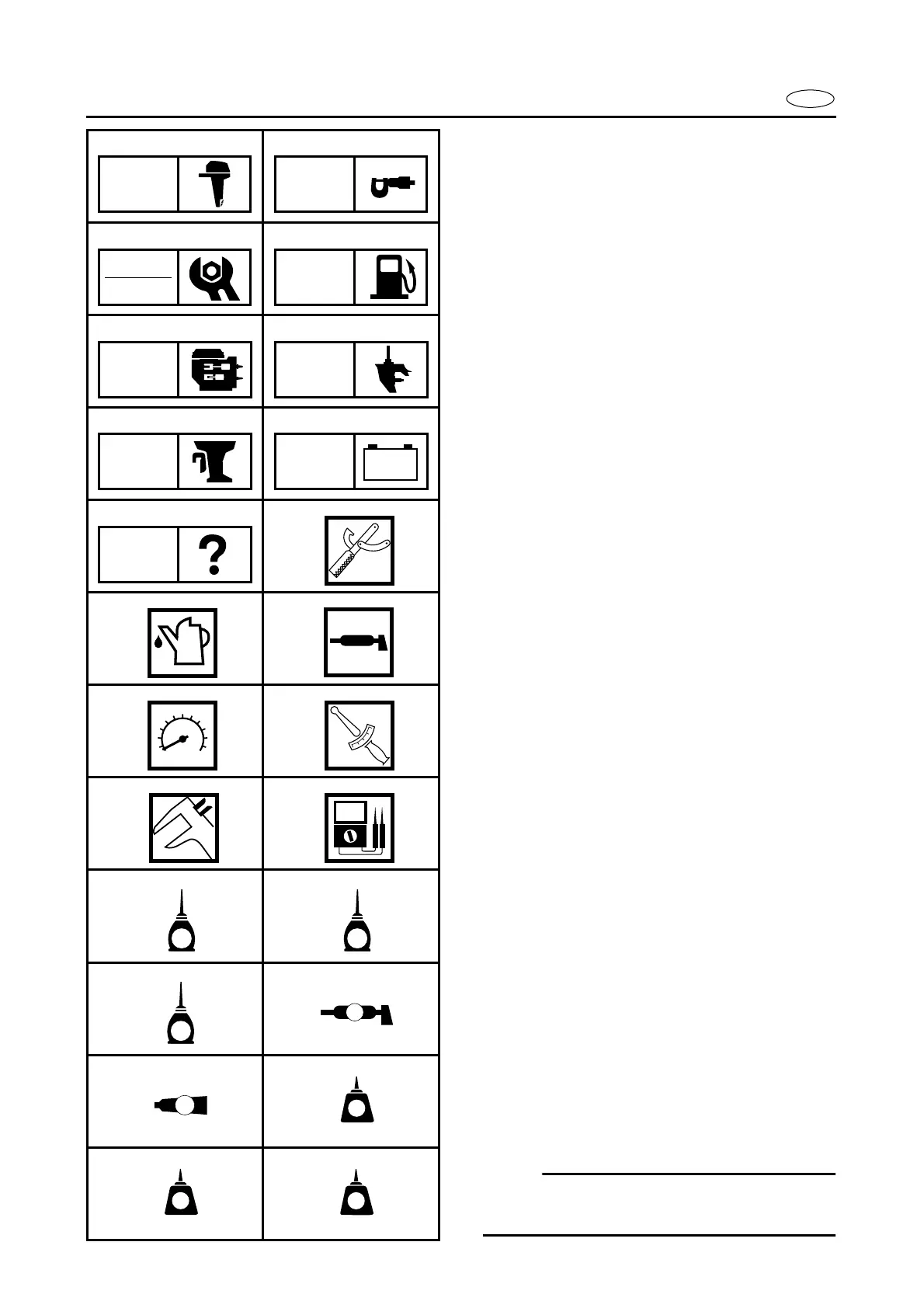
SYMBOLS
Symbols
1
to
9
are designed as thumb-
tabs to indicate the content of a chapter.
1
General Information
2
Specifications
3
Periodic Inspection and Adjustment
4
Fuel System
5
Power Unit
6
Lower Unit
7
Bracket Unit
8
Electrical Systems
9
Trouble Analysis
Symbols
0
to
F
indicates specific data:
0
Special service tool
A
Specified liquid
B
Specified grease
C
Specified engine speed
D
Specified torque
E
Specified measurement
F
Specified electrical value
[Resistance (
Ω
), Voltage (V),
Electric current (A)]
Symbol
G
to
J
in an exploded diagram
indicate grade of lubricant and location of
lubrication point:
G
Apply engine oil
H
Apply gear oil
I
Apply molybdenum disulfide oil
J
Apply water resistant grease (Yamaha
marine grease A, Yamaha marine grease)
Symbols
K
to
N
in an exploded diagram
indicate grade of sealing or locking agent,
and location of application point:
K
Apply Gasket Maker
L
Apply LOCTITE
No. 271 (Red LOCTITE)
M
Apply LOCTITE
No. 242 (Blue LOCTITE)
N Apply LOCTITE
No. 572
NOTE:
In this manual, the above symbols may not
be used in every case.
12
34
56
78
90
AB
CD
EF
GH
IJ
KL
MN
GEN
INFO
SPEC
INSP
ADJ
FUEL
POWR
LOWR
BRKT
–+
ELEC
TRBL
ANLS
T
R
.
.
E
G
M
A
GM
271
LT
242
LT
572
LT