5-20
POWR
E
ASSEMBLY AND ADJUSTMENT
G75500-0
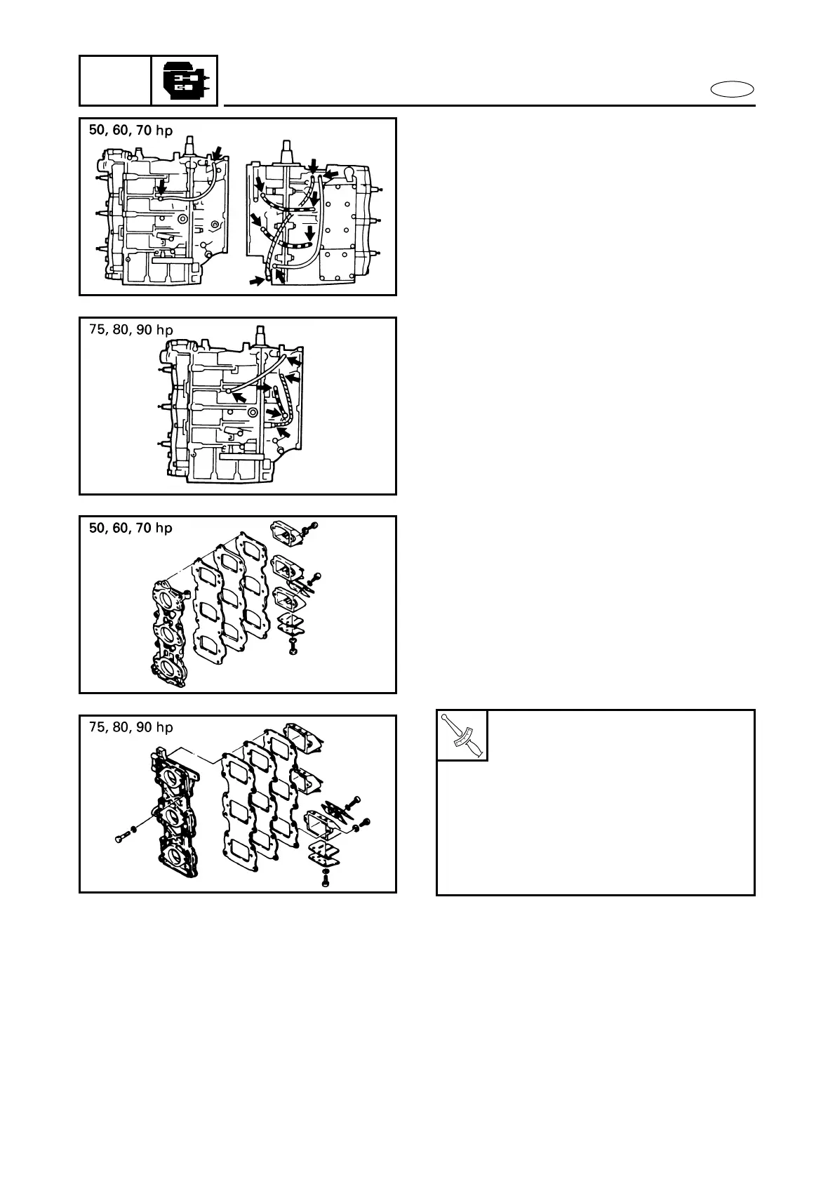
DRAINAGE HOSE
1. Fit two clips around the drainage hose.
2. Connect one end of the hose to the
delivery side of the check valve and the
other end to the joint on the intake side
and lock with the clips.
G76000-0*
INTAKE MANIFOLD
1. Install the reed-valve assembly and the
gasket reed-valve plate to the intake
manifold.
2. Install the manifold assembly to the
crankcase and tighten the bolts to the
specified torque in sequence and in two
steps.
T
R
.
.
Intake manifold (50, 60, 70 hp):
1st step:
4 Nm (0.4 m • kg, 2.9 ft • lb)
2nd step:
8 Nm (0.8 m • kg, 5.8 ft • lb)
Intake manifold (75, 80, 90 hp):
1st step:
4 Nm (0.4 m • kg, 2.9 ft • lb)
2nd step:
12 Nm (1.2 m • kg, 8.7 ft • lb)
G77000-0*
FUEL SYSTEM AND ELECTRICAL
SYSTEM
1. Install the fuel system.
Refer to “FUEL SYSTEM” section in
chapter 4.
2. Install the electrical system.
Refer to “ELECTRICAL COMPONENTS”
section in chapter 8.