7-30
E
BRKT
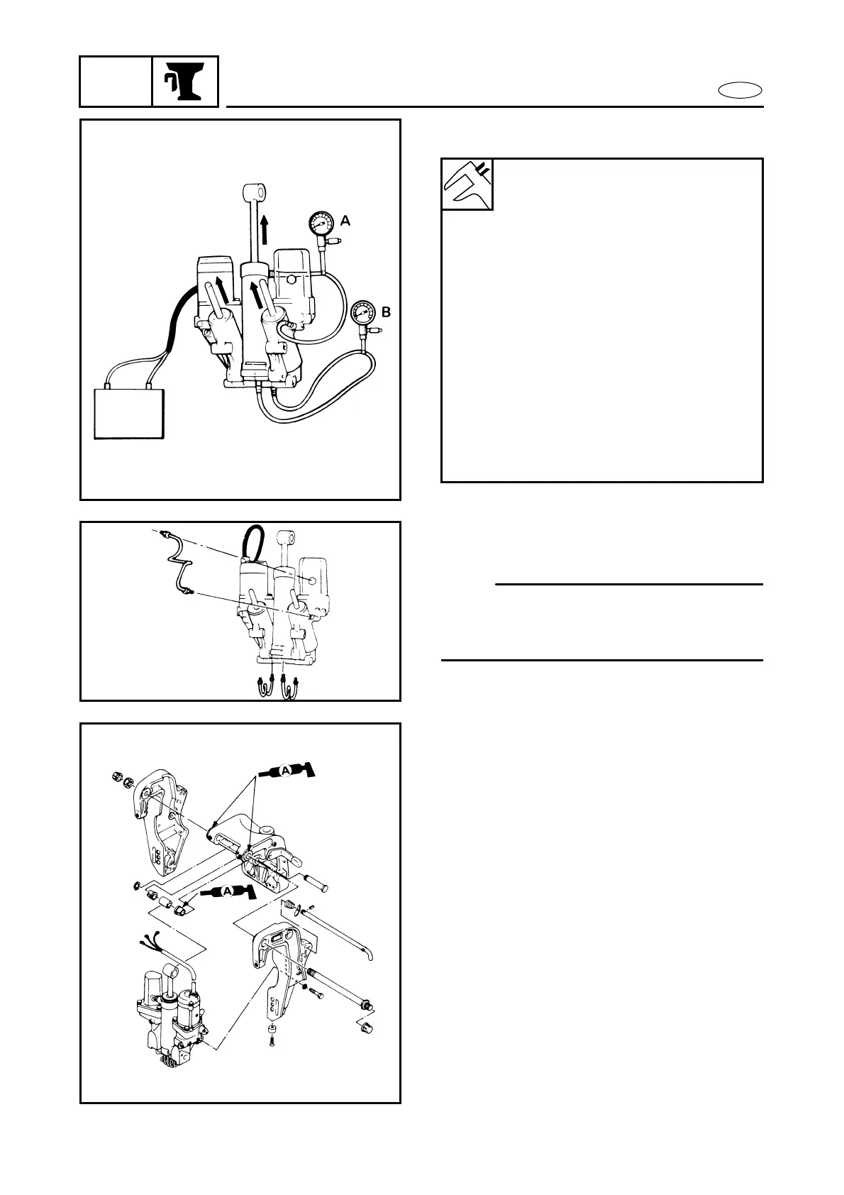
POWER TRIM AND TILT UNIT
A: Tilt operating pressure
B: Trim operating pressure
During up operation pressure:
A: 0 ~ 500 kPa
(0 ~ 5 kg/cm
2
, 0 ~ 71 psi)
B: 0 ~ 500 kPa
(0 ~ 5 kg/cm
2
, 0 ~ 71 psi)
At the end of up-operation pres-
sure:
A: 0 kPa (0 kg/cm
2
, 0 psi)
[6H308]
B: 3,500 ~ 4,500 kPa
(35 ~ 45 kg/cm
2
, 500 ~ 640 psi)
[6H1-15]
B: 9,000 ~ 11,000 kPa
(90 ~ 110 kg/cm
2
,
1,280 ~ 1,565 psi)
[62F-02]
B: 5,690 ~ 6,570 kPa
(57 ~ 66 kg/cm
2
, 299 ~ 526 psi)
5. Remove the fluid pressure gauge and
install the delivery pipes.
NOTE:
When the fluid pressure gauge has been
removed, be sure to bleed the air from the
system.
K56000-0
INSTALLATION
1. Referring to the illustration, install the
power trim and tilt unit to the bracket.