3-7
INSP
ADJ
E
PERIODIC SERVICE
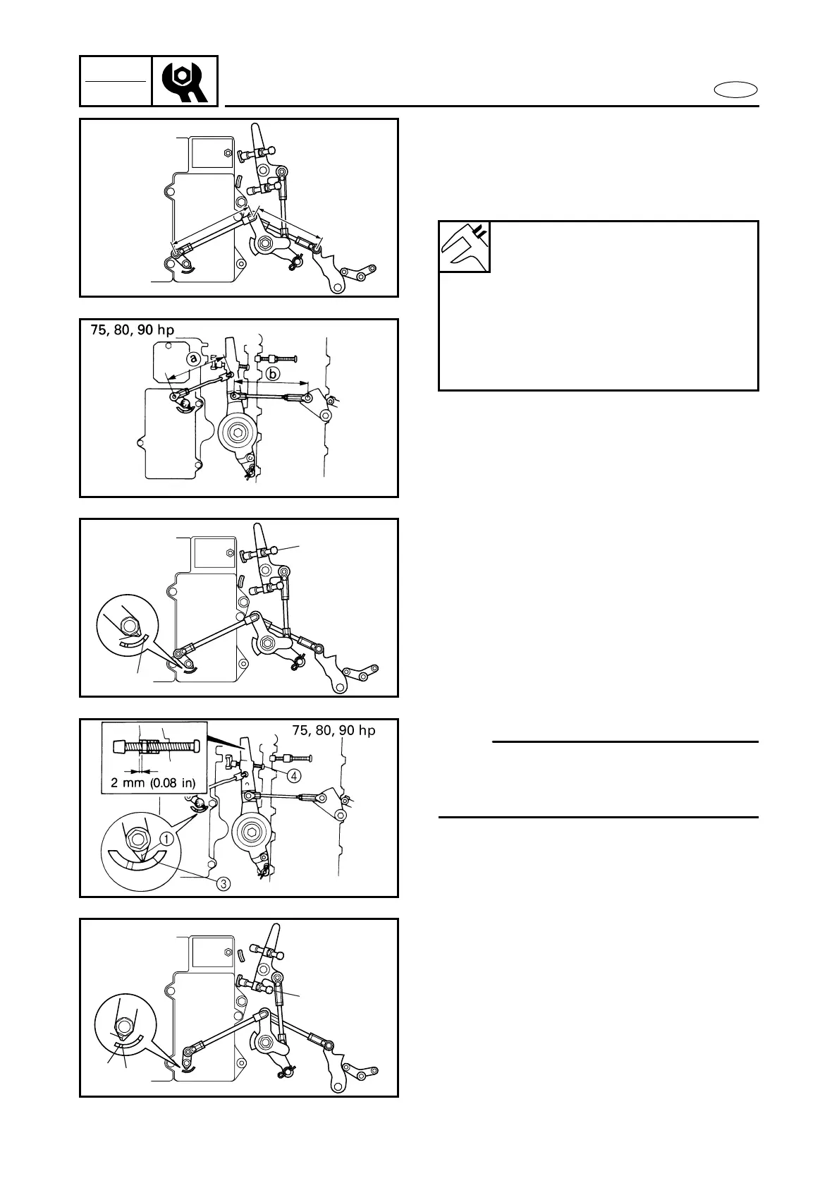
THROTTLE SENSOR CONTROL LINK
ADJUSTMENT
1. Adjust the lengths of the throttle sensor
control link and throttle cam control link
to specifications.
Throttle sensor control link
length
a
:
50, 60, 70 hp: 120
±
0.5 mm
(4.72
±
0.02 in)
75, 80, 90 hp: 93.5
±
0.5 mm
(3.68
±
0.02 in)
Throttle cam link length
b
:
50, 60, 70 hp: 95 mm (3.74 in)
75, 80, 90 hp: 120.5 mm (4.74 in)
50, 60, 70 hp
a
b
2. Adjust the length of the full-retard
adjusting screw so that when the full-
retard adjusting screw contacts the
stopper, the full-retard indication on the
CDI unit aligns with the timing indica-
tor.
1
Timing indicator
2
Full-retard indication (50, 60, 70 hp)
3
Full-retard indication (75, 80, 90 hp)
4 Full-retard adjusting screw
NOTE:
The nut in the magneto control lever should
be 2 mm (0.08 in) off from the end of the
magneto control lever.
1
2
4
50, 60, 70 hp
3. Adjust the length of the full-advance
adjusting screw so that when the full-
advance adjusting screw contacts the
stopper, the full-advance indication on
the CDI unit aligns with the timing indi-
cator.
1 Timing indicator
2 Full-advance indication (50, 60 hp)
3 Full-advance indication (70 hp)
4 Full-advance adjusting screw
1
2
3
4
50, 60, 70 hp