8-7
–+
ELEC
E
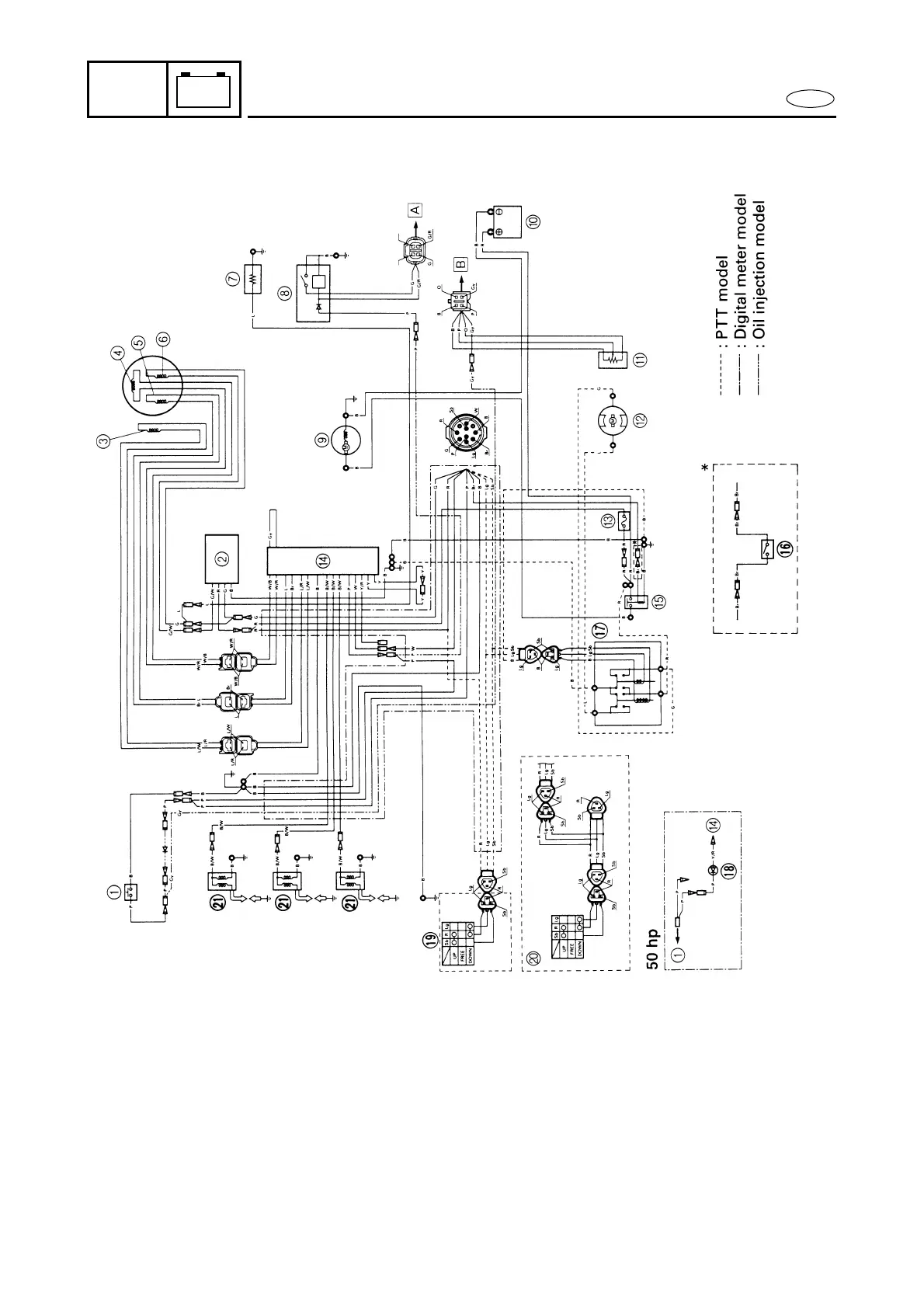
WIRING DIAGRAM
M30000-0
WIRING DIAGRAM
50, 60, 70 hp
1 Thermo switch
2 Rectifier/regulator
3 Crank position sensor
4 Pulser coil
5 Charge coil
6 Lighting coil
7 Electrothermal valve
(except for C60ER, C60TR)
8 Oil level sensor
(oil injection model)
9 Starter motor
0 Battery
A Trim sensor (PTT model)
B Power trim and tilt motor
(PTT model)
C Fuse (20A)
D CDI unit
E Starter relay
F Neutral switch
(P60TH/60FEHTO)
G Power trim and tilt relay
(PTT model)
H Oil warning lamp
(50GETO)
I Trailer switch (PTT model)
J Power trim and tilt switch
(P60TH/60FEHTO)
K Ignition coil
Å To oil level gauge
ı To trim gauge
B .........Black
Br ........Brown
G.........Green
Gy .......Gray
L..........Blue
O.........Orange
P..........Pink
R .........Red
Sb .......Sky blue
W ........White
Y .........Yellow
Lg .......Light green