7 - 33
–+
ELEC
LIGHTING SYSTEM
EAS00789
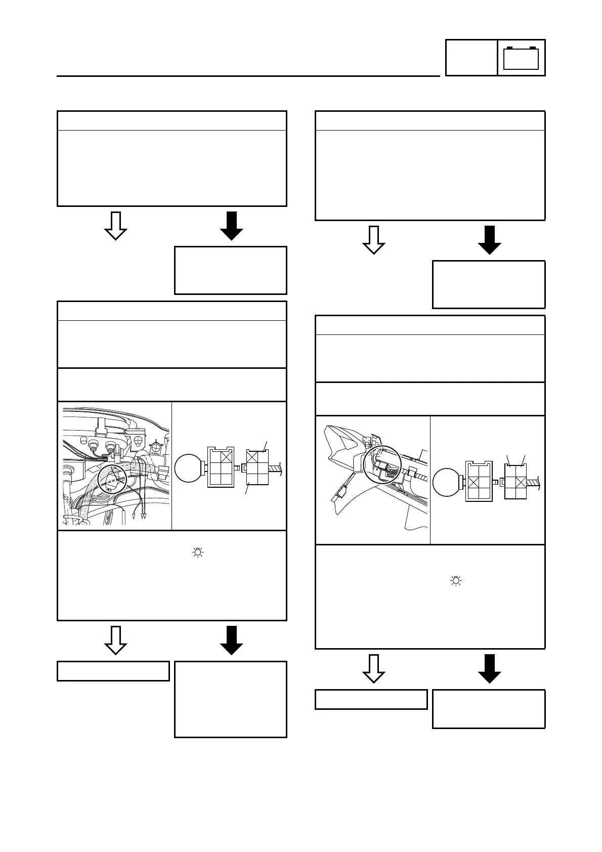
2. The meter light fails to come on.
EAS00790
3. The tail/brake light fails to come on.
1. Meter light bulb and socket
• Check the meter light bulb and socket for
continuity.
Refer to “CHECKING THE BULBS AND
BULB SOCKETS”.
• Are the meter light bulb and socket OK?
YES
NO
Replace the meter
light bulb, socket or
both.
2. Voltage
• Connect the pocket tester (DC 20 V) to the
meter light coupler (wire harness side) as
shown.
Positive tester probe
→
brown
1
Negative tester probe
→
black
2
• Set the main switch to “ON”.
• Set the light switch to “ ”.
• Measure the voltage (DC 12 V) of brown
1
on the meter light coupler (wire harness
side).
• Is the voltage within specification?
YES
NO
This circuit is OK. The wiring circuit
from the main switch
to the meter light
coupler is faulty and
must be repaired.
Br
G
Ch
B
Dg
B
Br
Dg
G
Ch
1
2
1. Tail/brake light bulb and socket
• Check the tail/brake light bulb and socket
for continuity.
Refer to “CHECKING THE BULBS AND
BULB SOCKETS”.
• Are the tail/brake light bulb and socket
OK?
YES
NO
Replace the tail/
brake light bulb,
socket or both.
2. Voltage
• Connect the pocket tester (AC 20 V) to the
tail/brake light coupler (wire harness side)
as shown.
Positive tester probe
→
blue
1
Negative tester probe
→
black
2
• Set the main switch to “ON”.
• Start the engine.
• Set the light switch to “ ”.
• Measure the voltage (AC 12 V) of blue
1
on the tail/brake light coupler (wire har-
ness side).
• Is the voltage within specification?
YES
NO
This circuit is OK. Replace the rectifier/
regulator.
B
Ch
L
Dg
Y
L
Dg
B
G/Y
Ch
12
 Loading...