7 - 36
– +
ELEC
SIGNALING SYSTEM
EAS00795 EAS00796
CHECKING THE SIGNALING SYSTEM
1. The horn fails to sound.
4. Wiring
• Check the entire signal system’s wiring.
Refer to “CIRCUIT DIAGRAM”.
• Is the signaling system’s wiring properly
connected and without defects?
YES
NO
Check the condition
of each of the signal-
ing system’s circuits.
Refer to “CHECK-
ING THE SIGNAL-
ING SYSTEM”.
Properly connect or
repair the signaling
system’s wiring.
1. Horn switch
• Check the horn switch for continuity.
Refer to “CHECKING THE SWITCHES”.
• Is the horn switch OK?
YES
NO
The horn switch is
faulty. Replace the
left handlebar switch.
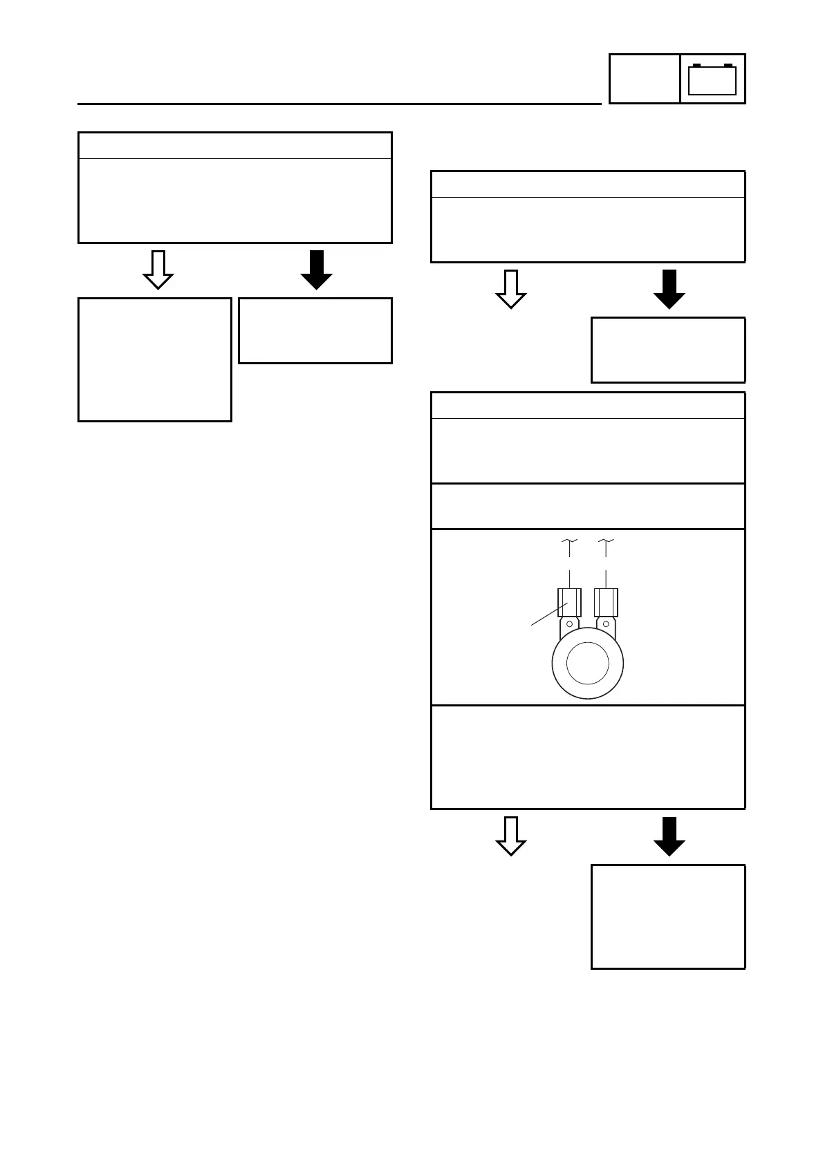
2. Voltage
• Connect the pocket tester (DC 20 V) to the
horn connector at the horn terminal as
shown.
Positive tester probe
→
brown
1
Negative tester probe
→
ground
• Set the main switch to “ON”.
• Push the horn switch.
• Measure the voltage (DC 12 V) of brown at
the horn terminal.
• Is the voltage within specification?
YES
NO
The wiring circuit
from the main switch
to the horn connector
is faulty and must be
repaired.
Br P
1