7 - 37
–+
ELEC
SIGNALING SYSTEM
EAS00798
2. The tail/brake light fails to come on.
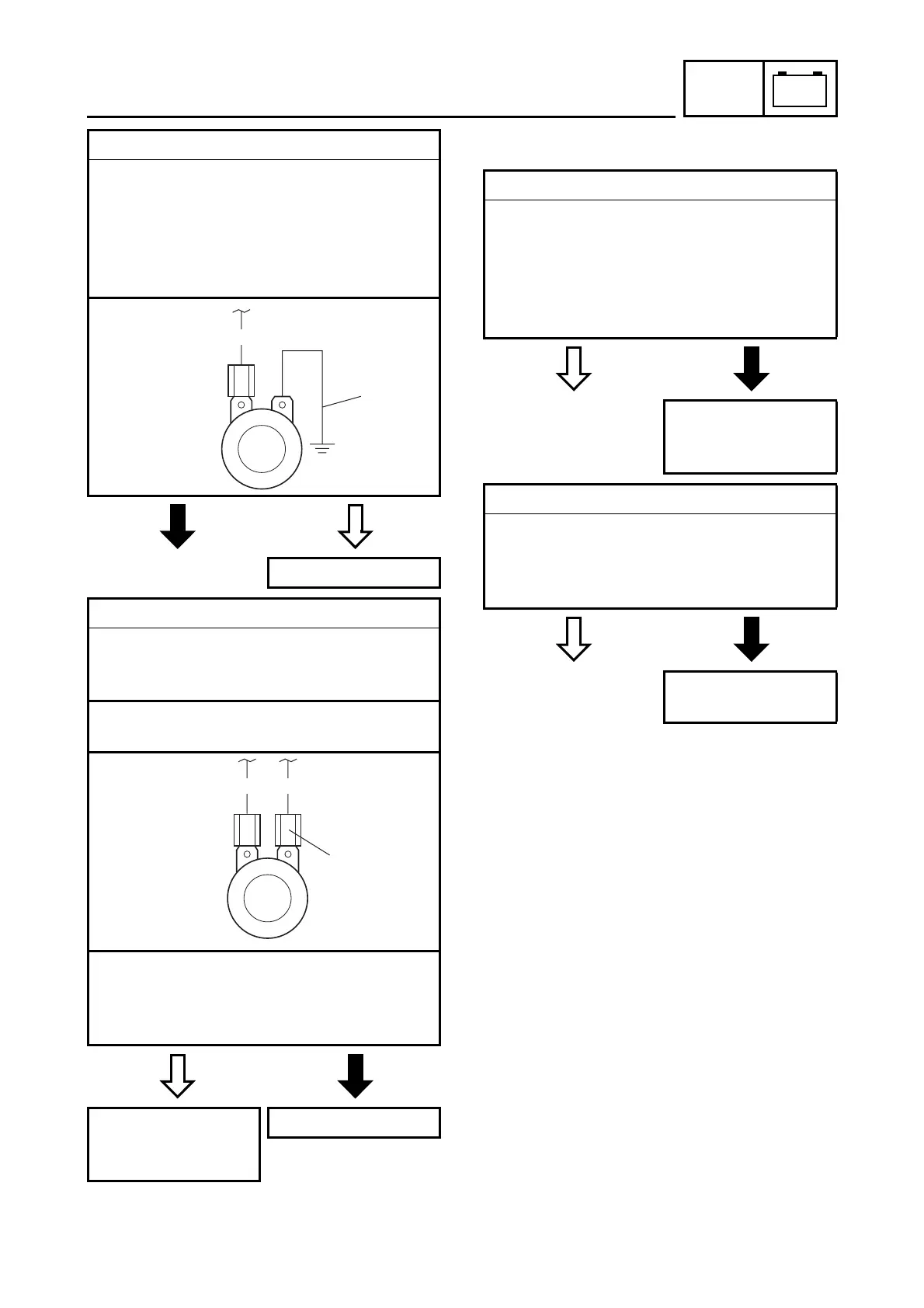
3. Horn
• Disconnect the pink connector at the horn
terminal.
• Connect a jumper lead
1
to the horn ter-
minal and ground the jumper lead.
• Set the main switch to “ON”.
• Does the horn sound?
NO
YES
The horn is OK.
4. Voltage
• Connect the pocket tester (DC 20 V) to the
horn connector at the pink terminal as
shown.
Positive tester probe
→
pink
1
Negative tester probe
→
ground
• Set the main switch to “ON”.
• Measure the voltage (DC 12 V) of pink
1
at the horn terminal.
• Is the voltage within specification?
YES
NO
Repair or replace the
pink lead or ground
lead.
Replace the horn.
Br
1
Br P
1
1. Tail/brake light bulb and socket
• Check the tail/brake light bulb and socket
for continuity.
Refer to “CHECKING THE BULBS AND
BULB SOCKETS”.
• Are the tail/brake light bulb and socket
OK?
YES
NO
Replace the tail/
brake light bulb,
socket or both.
2. Brake light switches
• Check the brake light switches for continu-
ity.
Refer to “CHECKING THE SWITCHES”.
• Is the brake light switch OK?
YES
NO
Replace the brake
light switch.