3 - 10
CHK
ADJ
ADJUSTING THE VALVE CLEARANCE/
ADJUSTING THE ENGINE IDLING SPEED
d. Hold the adjusting screw to prevent it from
moving and tighten the locknut to specifica-
tion.
e. Measure the valve clearance again.
f. If the valve clearance is still out of specifica-
tion, repeat all of the valve clearance adjust-
ment steps until the specified clearance is
obtained.
▲▲▲▲ ▲ ▲▲▲▲ ▲ ▲▲▲▲ ▲ ▲▲▲▲ ▲ ▲▲▲▲ ▲ ▲▲▲▲ ▲▲▲
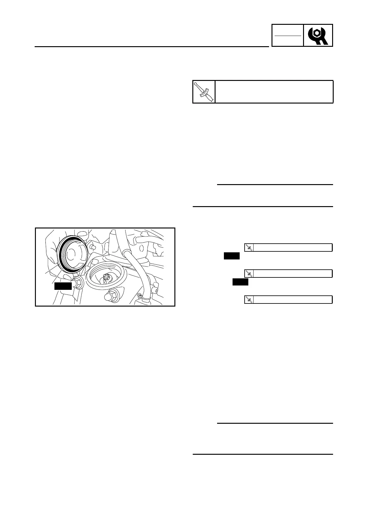
6. Install:
• rubber damper
NOTE:
Install the flap of the rubber damper securely in
the hole in the engine cooling fan cover.
T
R
.
.
Locknut
7 Nm (0.7 m · kg, 5.1 ft · lb)
7. Install:
• camshaft sprocket cover
• O-ring
• exhaust tappet cover
• O-ring 1
• intake tappet cover 2
8. Install:
• footboard
• front bottom cowling
• bottom cowling
• front cowling
Refer to “INSTALLING THE FRONT
COWLING AND LEG SHIELD”.
1
New
2
T
R
.
.
12 Nm (1.2 m · kg, 8.7 ft · lb)
New
T
R
.
.
18 Nm (1.8 m · kg, 13 ft · lb)
New
T
R
.
.
18 Nm (1.8 m · kg, 13 ft · lb)
EAS00054
ADJUSTING THE ENGINE IDLING SPEED
NOTE:
_
Prior to adjusting the engine idling speed, the
air filter element should be clean, and the
engine should have adequate compression.
1. Start the engine and let it warm up for sev-
eral minutes.