5-14
DC Injection Braking: b2
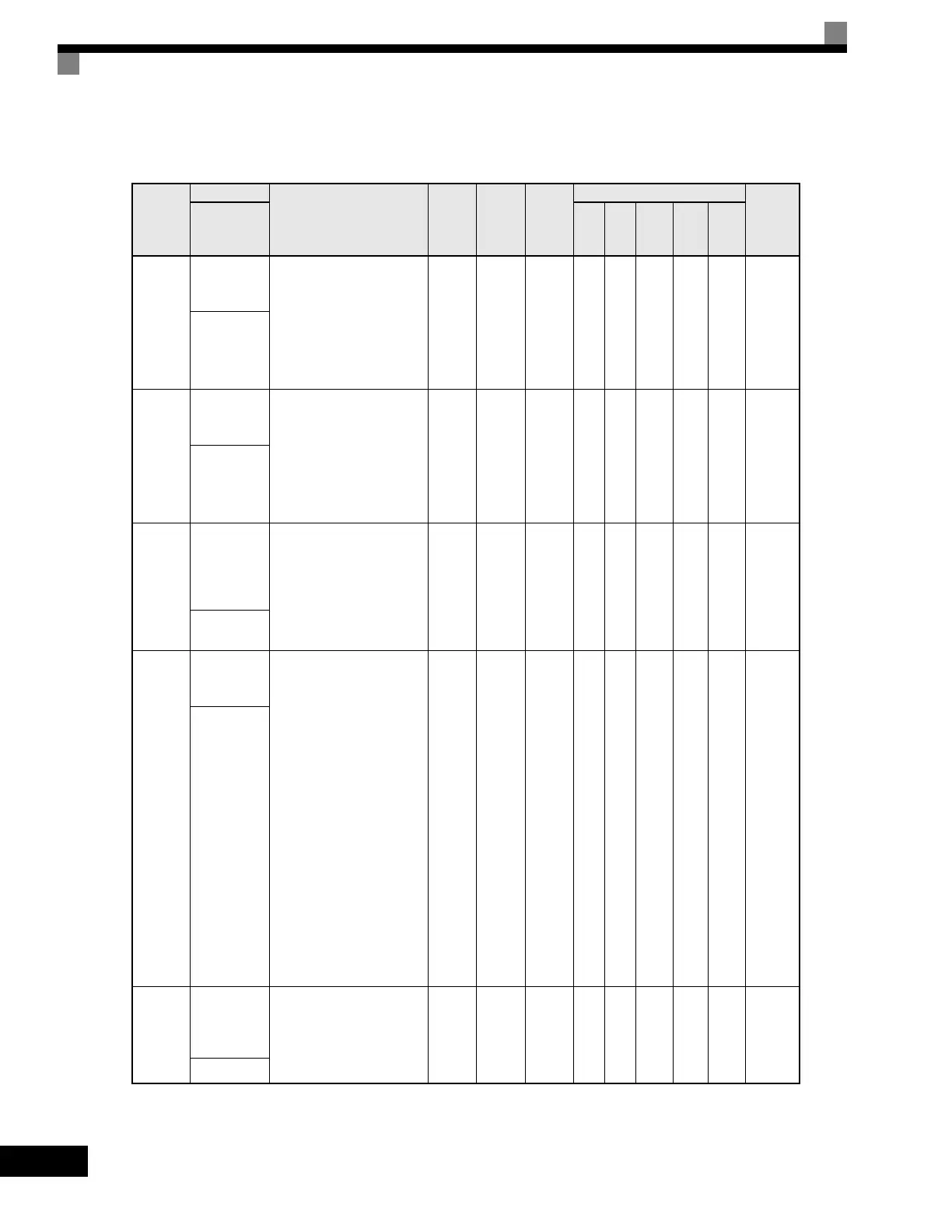
User parameters for injection braking are shown in the following table.
Parameter
Number
Name
Description
Setting
Range
Factory
Setting
Change
during
Operation
Control Methods
MODBUS
Register
Display
V/f
V/f
with
PG
Open
Loop
Vector
1
Flux
Vector
Open
Loop
Vector
2
b2-01
DC Injection
Braking Start
Frequency
Sets the frequency at which
DC injection braking starts
when ramp to stop
(b1-03 = 0) is selected.
If b2-01< E1-09, DC Injection
braking starts at E1-09.
Note: Zero Speed restrictions
are active in Flux Vector Mode.
0.0
to
10.0
0.5Hz No A A A A A 189H
DCInj Start
Freq
b2-02
DC Injection
Braking
Current
Sets the DC injection braking
current as a percentage of the
Drive rated current.
Note: The DC excitation
current is determined by the
setting in E2-03 when
operating in flux loop vector
control mode.
0
to
100
50% No A A A No No 18AH
DCInj
Current
b2-03
DC Injection
Braking
Time/DC
Excitation
Time at Start
Sets the time of DC injection
braking at start in units of
0.01 seconds.
0.00
to
10.00
0.00 s No A A A A A 18BH
DCInj
Time@Start
b2-04
DC Injection
Braking Time
at Stop
Sets the time length of DC
injection braking at stop in
units of 0.01 seconds.
1: When b1-03 = 2, actual
DC Injection time is
calculated as follows:
(b2-04) x 10 x
(OutputFreq) / (E1-04)
2: When b1-03 = 0, this
parameter determines the
amount of time DC
Injection is applied to the
motor at the end of the
decel ramp.
3: This should be set to a
minimum of 0.50 seconds
when using HSB. This will
activate DC injection during
the final portion of HSB and
help ensure that the motor
stops completely.
0.00
to
10.00
0.50 s No A A A A A 18CH
DCInj
Time@Stop
b2-08
Magnetic
Flux
Compensation
Capacity
Sets the magnetic flux
compensation as a percentage
of the no-load current value
(E2-03).
0
to
1000
0% No No No A No No 190H
Field Comp
Artisan Technology Group - Quality Instrumentation ... Guaranteed | (888) 88-SOURCE | www.artisantg.com

 Loading...


