6-128
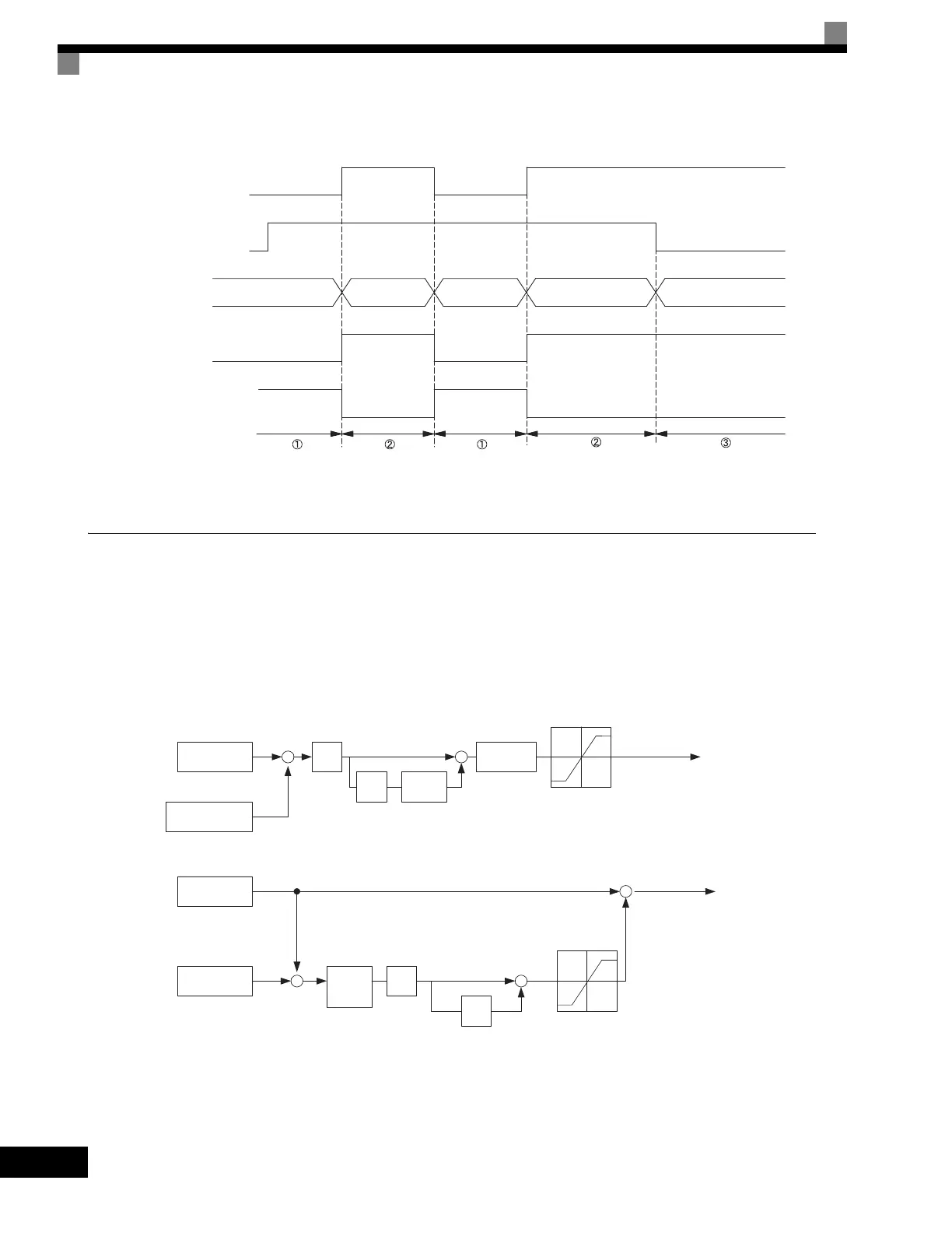
A timing chart for switching between speed and torque control is shown in the following figure.
Fig 6.66 Speed/Torque Control Switching Time Chart.
Speed Control (ASR) Structure
Speed control (ASR) during vector control adjusts the torque reference so that the deviation between the
speed reference and the estimated speed (PG feedback or speed estimator) is 0. Speed control (ASR) during V/
f control with a PG adjusts the output frequency so that the deviation between the speed reference and the esti-
mated speed (PG feedback or speed estimator) is 0. The following block diagram shows the structure of the
speed control for vector or V/f control with a PG.
Fig 6.67 Speed Control Block Diagrams
Speed/torque change signal
(terminal S8 input)
Run command
Control mode
Terminal A1 input
Terminal A3 input
Stop
OPEN
CLOSED
OPEN
CLOSED
Run
Speed Torque Speed Torque Speed (decel to stop)
Speed
reference
Speed limit
Speed
reference
Speed limit
Torque limit
Torque
reference
Torque limit
Torque
reference
Frequency
reference
Detected speed
Estimated speed
P
I
Torque limits
Torque reference
+
+
+
−
Speed Control Block Diagram for Vector Control
Frequency
reference
Detected speed
P
I
Change
rate
limiter
Limit
+
+
+
−
Speed Control Block Diagram for V/f Control with a PG
+
+
Output frequency
C5-0, C5-03
C5-02, C5-04
C5-06
I
limit
C5-08
Primary
filter
L7-01 to L7-04
C5-01
C5-03
C5-02, C5-04
C5-05
Artisan Technology Group - Quality Instrumentation ... Guaranteed | (888) 88-SOURCE | www.artisantg.com

 Loading...


