Wiring Main Circuit Terminals
2-13
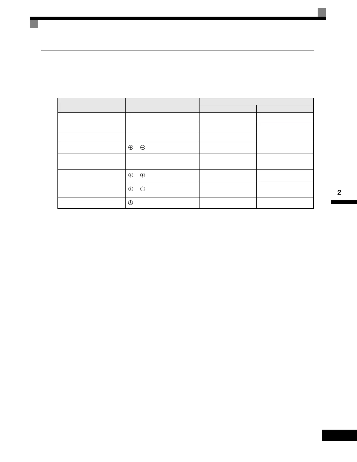
Main Circuit Terminal Functions
Main circuit terminal functions are summarized according to terminal symbols in Table 2.4. Wire the terminals
correctly for the desired purposes.
Table 2.4 Main Circuit Terminal Functions (200-240 V Class and 380-480 V Class)
Purpose Terminal Symbol
Model: CIMR-G7U
208-240 Vac 480 Vac
Main circuit power input
R/L1, S/L2, T/L3 20P4 to 2110 40P4 to 4300
R1/L11, S1/L21, T1/L31 2018 to 2110 4018 to 4300
Drive outputs U/T1, V/T2, W/T3 20P4 to 2110 40P4 to 4300
DC power input
1,
20P4 to 2110 40P4 to 4300
Braking Resistor Unit connec-
tion
B1, B2 20P4 to 27P5 40P4 to 4015
DC link choke connection
1, 2
20P4 to 2015 40P4 to 4015
Braking Transistor Unit con-
nection
3,
2018 to 2110 4018 to 4300
Ground 20P4 to 2110 40P4 to 4300
Artisan Technology Group - Quality Instrumentation ... Guaranteed | (888) 88-SOURCE | www.artisantg.com

 Loading...


