2-32
Installation
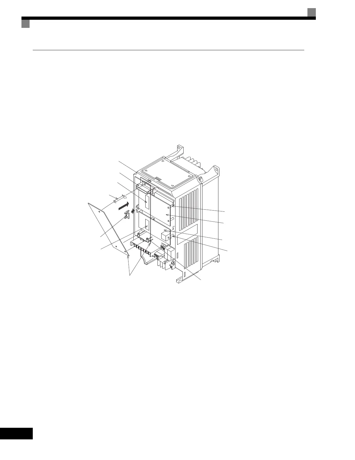
Before mounting an Option Board, remove power from the Drive and wait for the CHARGE LED to go out.
Remove the Digital Operator, front cover, and option clip. Option Clip can be easily removed by squeezing
the protruding portions of the clip and then pulling it out. Then, mount the Option Board(s).
The A Option Board uses a mounting spacer to secure the board to the control board. Insert the mounting
spacer as shown in Fig 2.18.
After installing an Option Board into slot C or D, insert the Option Clip to prevent the side with the connector
from rising.
Refer to documentation provided with the Option Board for detailed mounting instructions for option slots A,
C, and D.
Fig 2.18 Mounting Option Cards
A Option Card mounting spacer hole
4CN
A Option Card connector
2CN
C Option Card connector
A Option Card mounting spacer
(Provided with A Option Card.)
Option Clip
(To prevent raising of
C and D Option Cards)
3CN
D Option Card connector
A Option Card
A Option Card mounting spacer
D Option Card mounting spacer
C Option Card mounting spacer
D Option Card
C Option Card
Artisan Technology Group - Quality Instrumentation ... Guaranteed | (888) 88-SOURCE | www.artisantg.com

 Loading...


