User Parameter Tables
5-83
* Factory settings will vary based on drive capacity (values given here are for 208-240Vac, 0.4kW).
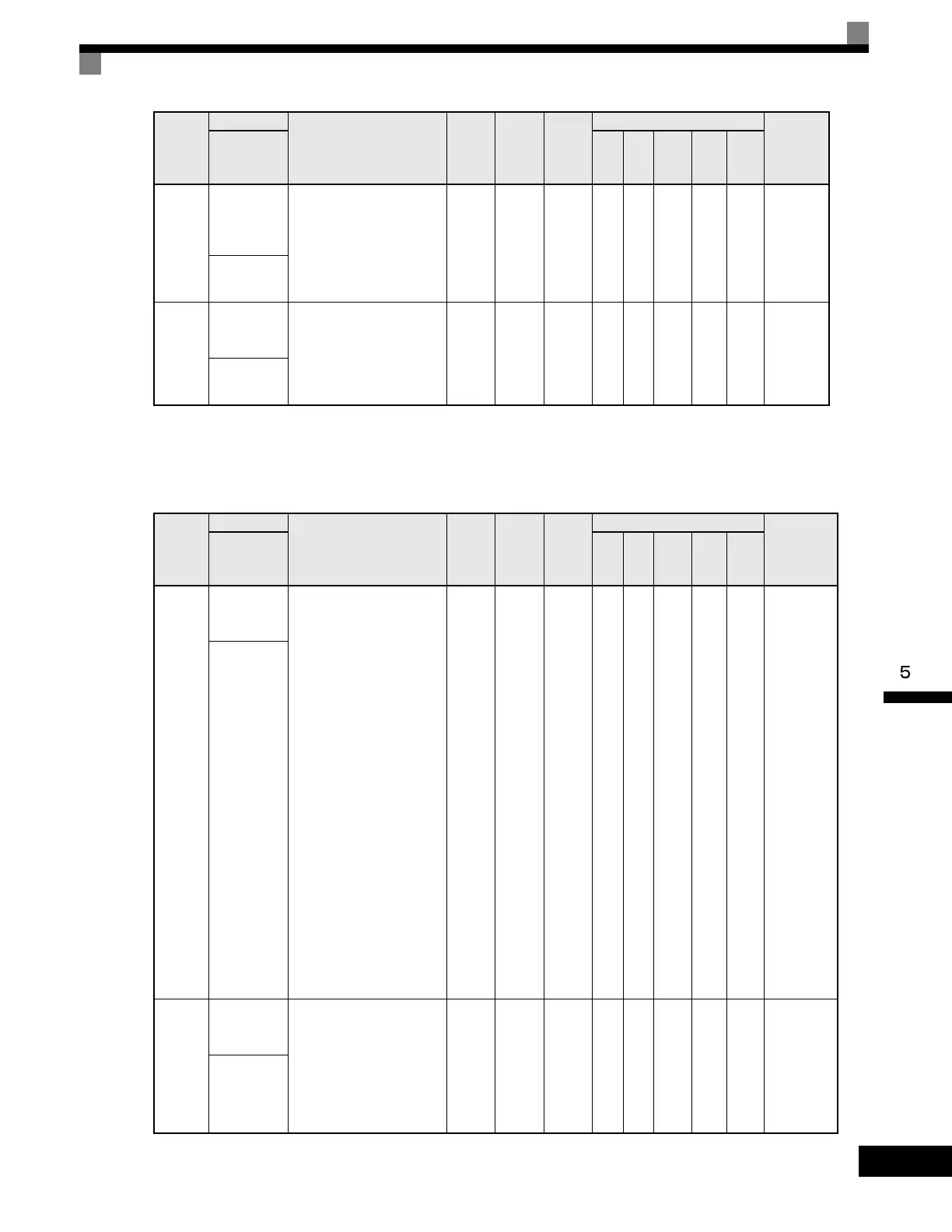
Copy Function: o3
User parameters for the copy function are shown in the following table.
o2-12
Fault Trace/
Fault History
Clear
Function
Clears the fault memory
contained in the U2 and U3
monitors.
0: Disabled - no effect
1: Enabled - resets U2 and
U3 monitors, and returns
o2-12 to zero.
0 to 1 0 No A A A A A 510H
Fault Trace
Init
o2-14
kWh User
Monitor
Initialization
Used to reset the kilowatt-
hour monitor U1-29 to zero.
0: Disabled - no change
1: Enabled - Resets U1-29 to
zero and returns o2-14 to
zero.
0 to 1 0 No A A A A A 512H
kWH
MonitorClear
Parameter
Number
Name
Description
Setting
Range
Factory
Setting
Change
during
Operation
Control Methods
MODBUS
Register
Display
V/f
V/f
with
PG
Open
Loop
Vector
1
Flux
Vector
Open
Loop
Vector
2
o3-01
Copy
Function
Selection
This parameter controls the
copying of parameters to and
from the Digital Operator.
0: COPY SELECT (no
function)
1: INV --> OP READ - All
parameters are copied
from the Drive to the
Digital Operator.
2: OP --> INV WRITE - All
parameters are copied
from the Digital Operator
to the Drive.
3: OP<-->INV VERIFY -
Parameter settings in the
Drive are compared to
those in the Digital
Operator.
Note:When using the copy
function, the Drive
model number (o2-04),
software number
(U1-14), and control
method (A1-02) must
match or an error will
occur.
0 to 3 0 No A A A A A 515H
Copy
Function Sel
o3-02
Copy
Allowed
Selection
Enables and disables the
Digital Operator copy
functions.
0: Disabled - No Digital
Operator copy functions
are allowed.
1: Enabled - Copying
allowed.
0 to 1 0 No A A A A A 516H
Copy
Allowable
Parameter
Number
Name
Description
Setting
Range
Factory
Setting
Change
during
Operation
Control Methods
MODBUS
Register
Display
V/f
V/f
with
PG
Open
Loop
Vector
1
Flux
Vector
Open
Loop
Vector
2
Artisan Technology Group - Quality Instrumentation ... Guaranteed | (888) 88-SOURCE | www.artisantg.com

 Loading...


