User Parameter Tables
5-103
Note Attach a Momentary Power Interruption Compensation Unit if compensation for power interruptions of up to 2.0 seconds is required for 208-240Vac
Drives with outputs of 0.4 to 7.5 kW.
* 1. The initial settings for C6-02 are as follows: 0: Low noise PWM, 1: 2.0 kHz, 2: 5.0 kHz, 3: 8.0 kHz, 4: 10 kHz, 5: 12.5 kHz, and 6: 15 kHz. If the carrier
frequency is set higher than the factory setting for Drives with outputs of 5.5 kW or more, the Drive rated current will need to be reduced.
* 2. The initial settings for C6-11 are as follows: 1: 2.0 kHz, 2: 4.0 kHz, 3: 6.0 kHz, 4: 8.0 kHz.
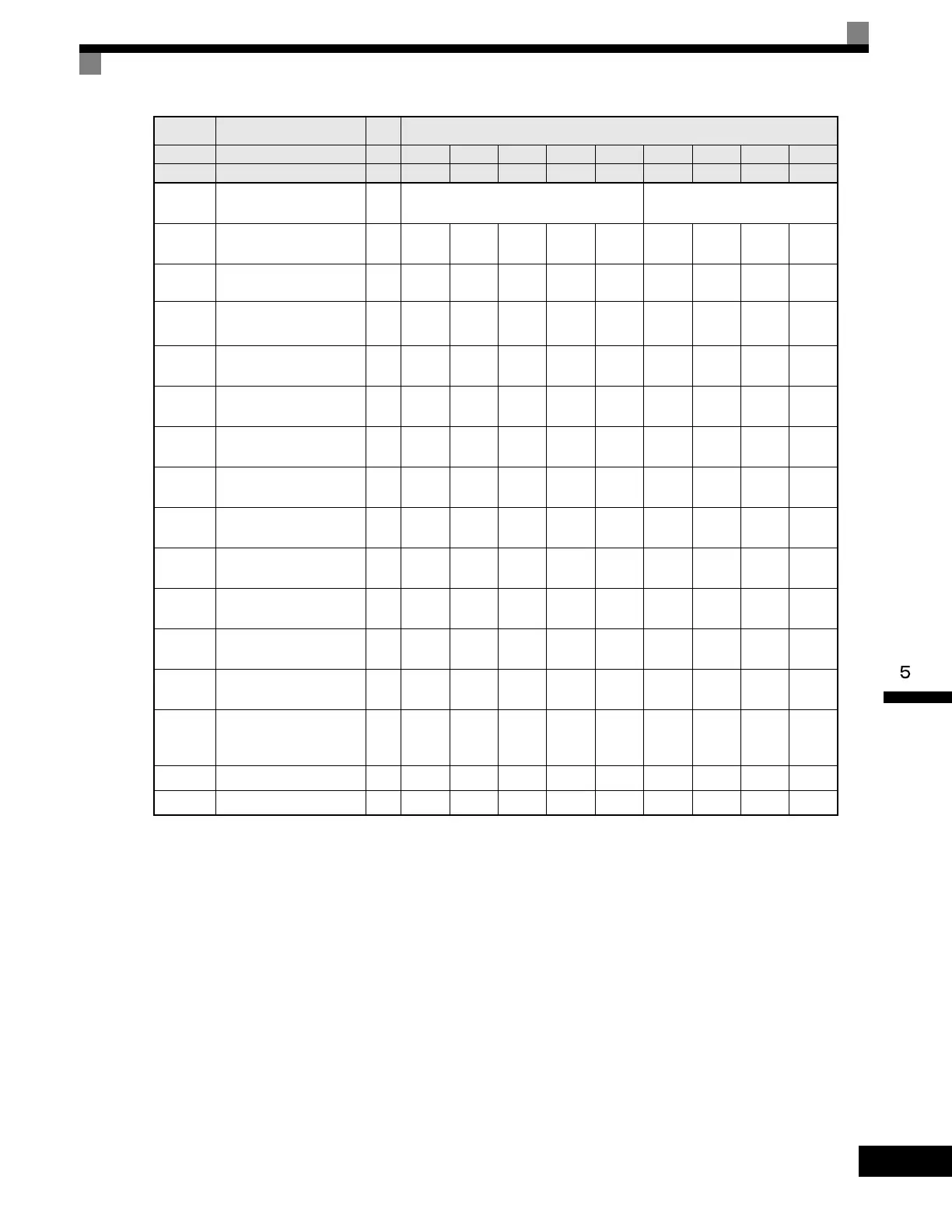
Parameter
Number
Name Unit Factory Setting
- Drive Capacity kW 18.5 22 30 37 45 55 75 90 110
o2-04 kVA selection - 9 A B C D E F 10 11
b8-03
Energy Saving Control
Filter Time Constant
s 0.50 (Open-loop vector control) 2.00 (Open-loop vector control)
b8-04
Energy Saving Coefficient
Va lu e
- 57.87 51.79 46.27 38.16 35.78 31.35 23.10 20.65 18.12
C6-02
Carrier Frequency Selection
*1
-644444411
C6-11
Carrier Frequency Selection
for Open Loop Vector 2
*2
-333333311
-
Carrier frequency selection
upper limit
-664444411
E2-01
(E4-01)
Motor Rated Current A 65.8 77.2 105.0 131.0 160.0 190.0 260.0 260.0 260.0
E2-02
(E4-02)
Motor Rated Slip Hz 1.67 1.70 1.80 1.33 1.60 1.43 1.39 1.39 1.39
E2-03
(E4-03)
Motor No-Load Current A 15.7 18.5 21.9 38.2 44.0 45.6 72.0 72.0 72.0
E2-05
(E4-05)
Motor Line-to-Line
Resistance
Ω 0.101 0.079 0.064 0.039 0.030 0.022 0.023 0.023 0.023
E2-06
(E4-06)
Motor Leakage Inductance % 20.1 19.5 20.8 18.8 20.2 20.5 20.0 20.0 20.0
E2-10
Motor Iron Loss for Torque
Compensation
W 505 538 699 823 852 960 1200 1200 1200
L2-02
Momentary Power Loss
Ride-thru Time
s 2.0 2.0 2.0 2.0 2.0 2.0 2.0 2.0 2.0
L2-03
Momentary Power Loss
Minimum Base Block Time
s 1.0 1.1 1.1 1.2 1.2 1.3 1.5 1.7 1.7
L2-04
Momentary Power Loss
Voltage Recovery Ramp
Time
s 0.6 0.6 0.6 0.6 1.0 1.0 1.0 1.0 1.0
L8-02 Overheat Alarm Level °C 90 90 95 100 100 110 100 95 95
n5-02 Motor Acceleration Time s 0.317 0.355 0.323 0.320 0.387 0.317 0.533 0.592 0.646
Artisan Technology Group - Quality Instrumentation ... Guaranteed | (888) 88-SOURCE | www.artisantg.com

 Loading...


