6-80
*
1
In order to adjust the meter, 100% of the appropriate output is multiplied for the gain setting, the bias amount is added and then output.
See H4-02 when stopped in Quick, Advanced, or Verify mode. If 03 appears on the setting screen, then terminal FM is used.
See H4-04 when stopped in Quick, Advanced, or Verify mode. If 06 appears on the setting screen, then terminal AM is used.
*
2
Setting "2: 4 to 20mA" is not available in F7A
*
3
In order to adjust the meter, 100% of the appropriate output is multiplied for the gain setting, and the bias amount is added and then output.
See F4-02 when stopped in Quick, Advanced, or Verify mode. If 05 appears on the setting screen, then CH1 is used.
See F4-04 when stopped in Quick, Advanced, or Verify mode. If 06 appears on the setting screen, then CH2 is used.
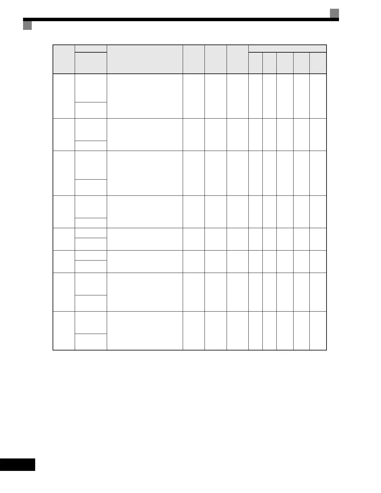
F4-01
AO-08/AO-
12 Channel 1
Monitor
Selection
Sets the number of the monitor item
to be output. (U1-oo)
The following settings cannot be
used:
4, 10 to 14, 25, 28, 29, 30, 34, 35,
39, 40, 41.
1 to 45 2 No A A A A A
AO Ch1
Select
F4-02
AO-08/AO-
12 Channel 1
Gain
Sets the channel 1 gain.
Ex: Set F4-02 = 50% to output
100% at 5.0V output.
0.00
to
1000.0
100.0% Yes A A A A A
AO Ch1 Gain
F4-03
AO-08/AO-
12 Channel 2
Monitor
Selection
Sets the number of the monitor item
to be output. (U1-xx)
The following settings cannot be
set:
4, 10 to 14, 25, 28, 29, 30, 34, 39,
40, 41.
1 to 45 3 No A A A A A
AO Ch2
Select
F4-04
AO-08/AO-
12 Channel 2
Gain
Sets the channel 2 gain. *
3
Ex: Set F4-04 = 50% to output
100% at 5.0V output.
0.00
to
1000.0
50.0% Yes A A A A A
AO Ch2 Gain
F4-05
AO Ch1 Bias Sets the channel 1 bias (100%/10V).
Ex: Set F4-05 = 50% to output 0%
at 5.0V output.
-110.0
to
110.0
0.0% Yes A A A A A
AO Ch1 Bias
F4-06
AO Ch2 Bias Sets the channel 2 bias (100%/10V).
Ex: Set F4-06 = 50% to output 0%
at 5.0V output.
-110.0
to
110.0
0.0% Yes A A A A A
AO Ch2 Bias
F4-07
AO-12
Channel 1
Signal Level
Sets the range of the voltage
output.
0: 0 to 10Vdc
1: -10 to +10Vdc
0 to 1 0 NoAAAAA
AO Opt
Level Sel
F4-08
AO-12
Channel 2
Signal Level
Sets the range of the voltage
output.
0: 0 to 10Vdc
1: -10 to +10Vdc
0 to 1 0 NoAAAAA
AO Opt
Level Sel
Parameter
Number
Name
Description
Setting
Range
Factory
Setting
Change
during
Operation
Control Methods
Display
V/f
V/f
with
PG
Open
Loop
Vector
1
Flux
Vector
Open
Loop
Vector
2
Artisan Technology Group - Quality Instrumentation ... Guaranteed | (888) 88-SOURCE | www.artisantg.com

 Loading...


