Individual Functions
6-121
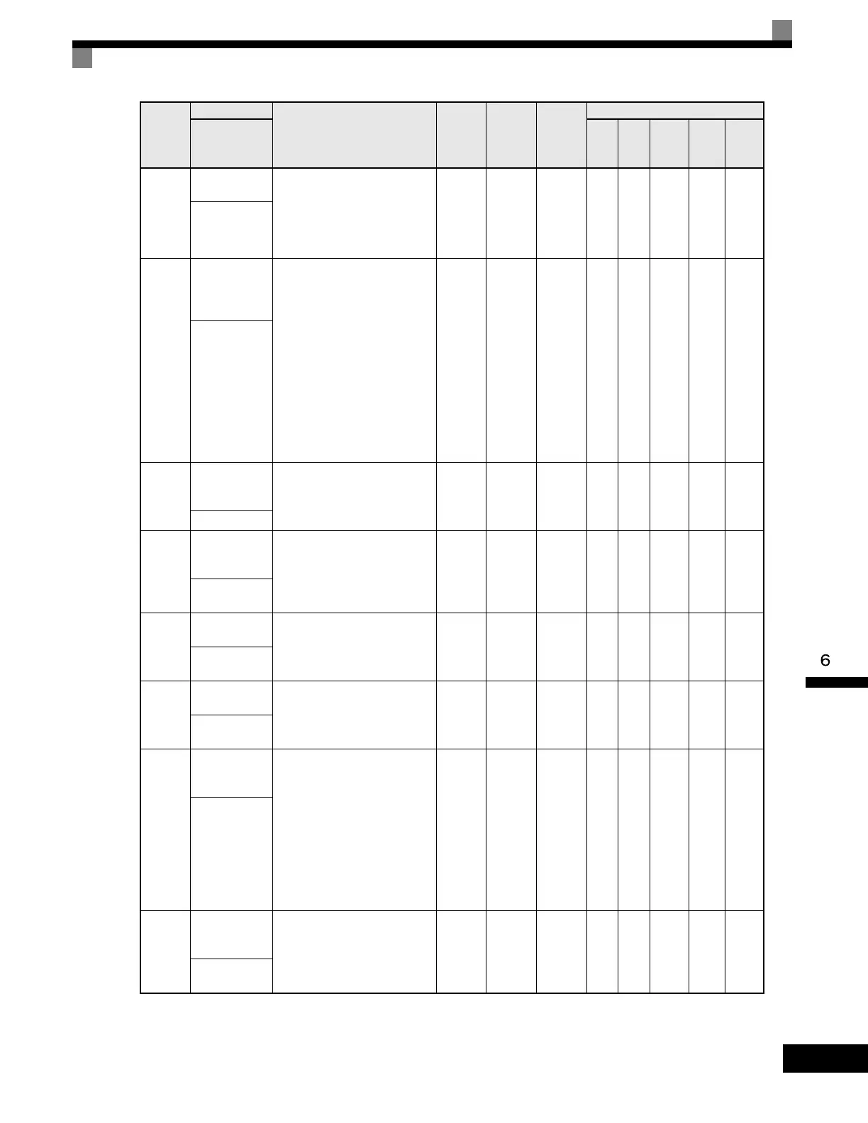
d5-05
Speed Limit
Bias
Sets the speed limit bias as a
percentage of the maximum
output frequency (E1-04). Bias is
given to the specified speed limit.
It can be used to adjust the margin
for the speed limit.
0 to 120 10% No No No No A A
Speed Lmt Bias
d5-06
Speed/Torque
Control
Switchover
Timer
Sets the delay time from inputting
the multi-function input "speed/
torque control change" (from On
to OFF or OFF to ON) until the
control is actually changed. This
function is enabled when the
multi-function input "speed/
torque control change"
(H1-xx= 71) is set. While in the
speed/torque control switching
timer, the analog inputs hold the
value present when the "speed/
torque control change" is
received.
0
to
1000
0ms No No No No A A
Ref Hold Time
H3-04
Terminal A3
Signal Level
Selection
Sets the signal level of terminal
A3.
0: 0 to 10Vdc
1: -10 to +10Vdc
0 to 1 0 NoAAAAA
Term A3 Signal
H3-05
Terminal A3
Function
Selection
[Refer to table "H3-05, H3-09
Settings" for multi-function
selections]
0 to 1F 2 No A A A A A
Terminal A3
Sel
H3-06
Terminal A3
Gain Setting
Sets the output level when 10V is
input.
0.0
to
1000.0
100.0% Yes A A A A A
Terminal A3
Gain
H3-07
Terminal A3
Bias Setting
Sets the frequency reference when
0V is input.
-100.0
to
+100.0
0.0% Yes A A A A A
Terminal A3
Bias
H3-08
Terminal A2
Signal Level
Selection
Selects the signal level of terminal
A2.
0: 0 to 10Vdc (switch S1-2 must
be in the OFF position).
1: -10 to +10Vdc (switch S1-2
must be in the OFF position).
2: 4 to 20mA (switch S1-2 must
be in the ON position)
Note: Switch between current or
voltage inputs by using (S1-2)
switch on the terminal board.
0 to 2 2 NoAAAAA
Term A2 Signal
H3-09
Terminal A2
Function
Selection
Selects the function of terminal
A2.
Same choices as Terminal A3
Function Selection (H3-05).
0 to 1F 0 No A A A A A
Terminal A2
Sel
Parameter
Number
Name
Description
Setting
Range
Factory
Setting
Change
during
Operation
Control Methods
Display
V/f
V/f
with
PG
Open
Loop
Vector
1
Flux
Vector
Open
Loop
Vector
2
Artisan Technology Group - Quality Instrumentation ... Guaranteed | (888) 88-SOURCE | www.artisantg.com

 Loading...


