6-124
Speed Limiter and Priority Circuit (Speed Limit Function)
If the external torque reference and load are not balanced during torque control, the motor will accelerate in either the
forward or reverse direction. The speed limit function is used to limit the speed to a specified value and it consists of
the speed limiter circuit and priority circuit.
Application Precautions
There are two ways to set a speed limit: using an input from an analog input terminal and setting a speed limit in d5-04.
The inputs methods for a speed limit are listed in the following table.
Speed Limit Bias Setting
The speed limit bias can be set to limit both the forward and reverse speed to the same value. This differs from the
operation of the speed limit setting. To use the speed limit bias, set d5-04 to 0 and set the bias in d5-05 as a percentage
of the maximum output frequency.
To set 50% forward and reverse speed limits, set the speed limit setting to 0 (d5-03 = 2, d5-04 = 0, and d5-05 = 50).
The range of torque control will be from -50% to 50% of the maximum output speed.
When using both the speed limit and the speed limit bias, the range of torque control will be positive and negative
speed limits with the speed limit bias added to each.
The range of torque control when the forward speed limit is 50% and the speed limit bias is 10% is shown in the fol-
lowing figure. This figure does not take the priority circuit into account.
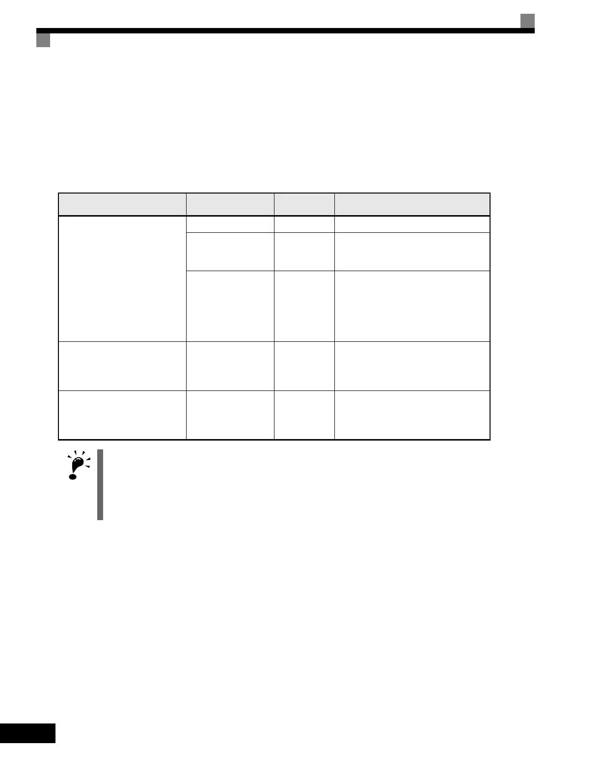
Speed Limit Input Method
Location of
Reference
Parameter
Settings
Remarks
Voltage input (0 to ±10 V)
Set in d5-04 d5-03 = 2 -
Between A1 and AC
b1-01 = 1
H3-01 = 1
Set H3-01 to 0 if the speed limit is always
to be positive.
Between A2 and AC
b1-01 = 0
H3-08 = 1
H3-09 = 1
The value will be added to the value input
on A1 to determine the speed limit.
Set H3-03 to 0 if the speed limit input on
A2 is always to be positive.
Turn OFF (V side) pin 2 of DIP switch S1
on the terminal board.
Current input (4 to 20mA) Between A2 and AC
b1-01 = 0
H3-08 = 2
H3-09 = 1
The value will be added to the value input
on A1 to determine the speed limit.
Turn ON (I side) pin 2 of DIP switch S1
on the terminal board.
Option Card (AI-4B)
(0 to ±10 V)
Between TC1 and TC4
b1-01 = 3
F2-01 = 0
If H3-09 is set to 0, the sum of the input
between TC2 and TC4 will be added the
input between TC1 and TC4 to determine
the speed limit.
The direction in which speed is controlled is determined by the sign of the speed limit signal and the direction
of the run command.
• Positive voltage applied: The speed in the forward direction will be limited for forward operation.
• Negative voltage applied: The speed in the reverse direction will be limited for reverse operation.
If the direction of motor rotation and the command direction are not the same, speed will be limited to 0 as
long as b5-05 is set to 0.
Artisan Technology Group - Quality Instrumentation ... Guaranteed | (888) 88-SOURCE | www.artisantg.com

 Loading...


