Options
6-153
* Factory setting will change according to the control mode (factory settings for Vector Control w/PG are shown here).
Using PG Speed Control Card
There are four types of PG Speed Control Card that can be used in V/f control with PG.
• PG-A2: A-phase (single) pulse input, compatible with open collector or complimentary outputs.
• PG-B2: A/B-phase pulse input, compatible with complimentary outputs.
• PG-D2: A-phase (single) pulse input, compatible with line drivers.
• PG-X2: A/B/Z-phase pulse input, compatible with line drivers.
There are two types of PG Speed Control Cards that can be used for flux vector control.
• PG-B2: A/B phase pulse inputs, complementary outputs
• PG-X2: A/B/Z phase pulse inputs, line driver outputs
For the connection diagram, refer to page 2-36.
Setting Number of PG Pulses
Set the number of PG (Pulse Generator/Encoder) pulses in pulses/rotation. Set the number of A-phase or B-
phase pulses per 1 motor rotation in F1-01.
Matching PG Rotation Direction and Motor Rotation Direction
Parameter F1-05 matches the PG rotation direction and the motor rotation direction. If the motor is rotating
forwards, set whether it is A-phase driven or B-phase driven. Make this setting when using PG-B2 or PG-X2.
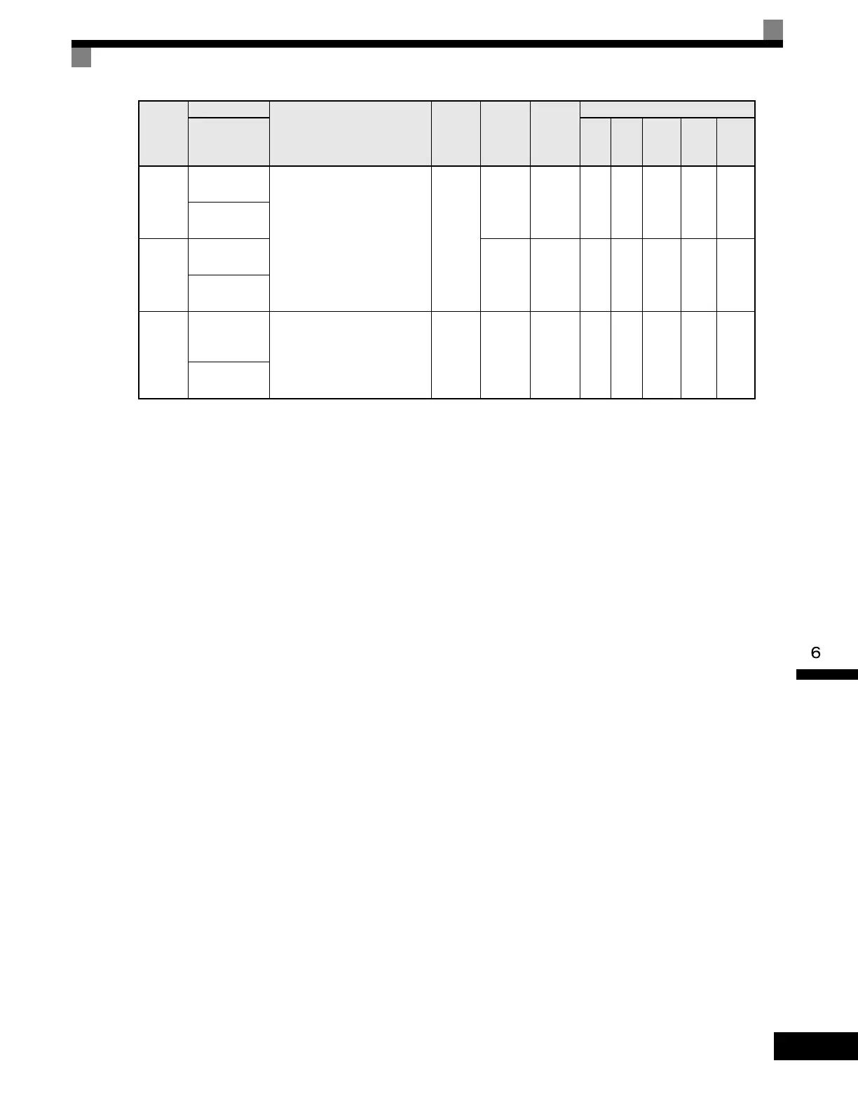
F1-12
Number of PG
Gear Teeth 1
Sets the gear ratio between the
motor shaft and the encoder (PG).
A gear ratio of 1 will be used if
either of these parameters is set to
0. This function is not available in
flux vector control.
0
to
1000
0 No No A No No No
PG # Gear
Teeth1
F1-13
Number of PG
Gear Teeth 2
0 No No A No No No
PG # Gear
Teeth2
F1-14
PG Open-Cir-
cuit Detection
Time
Configures the PG open (PGO)
function. PGO will be detected if
no PG pulses are detected for a
time longer than F1-14. See
F1-02.
0.0
to
10.0
2.0sec No No A No A No
PGO Detect
Time
Parameter
Number
Name
Description
Setting
Range
Factory
Setting
Change
during
Operation
Control Methods
Display
V/f
V/f
with
PG
Open
Loop
Vector
1
Flux
Vector
Open
Loop
Vector
2
Artisan Technology Group - Quality Instrumentation ... Guaranteed | (888) 88-SOURCE | www.artisantg.com

 Loading...


