Wiring Main Circuit Terminals
2-17
Installing a Magnetic Contactor
If the power supply for the main circuit is to be shut off during a sequence, a magnetic contactor can be used.
When a magnetic contactor is installed on the primary side of the main circuit to forcibly stop the Drive,
however, the regenerative braking does not work and the Drive will coast to a stop.
• The Drive can be started and stopped by opening and closing the magnetic contactor on the primary side.
Frequently opening and closing the magnetic contactor, however, may cause the Drive to break down. Start
and stop the Drive at most once every 30 minutes.
• When the Drive is operated with the Digital Operator, automatic operation cannot be performed after
recovery from a power interruption.
• If the Braking Resistor Unit is used, program the sequence so that the magnetic contactor is turned OFF by
the contact of the Unit's thermal overload relay.
Connecting Input Power Supply to the Terminal Block
Input power supply can be connected to any terminal R/L1, S/L2, or T/L3 on the terminal block; the phase
sequence of input power supply is irrelevant to the phase sequence.
Installing an AC Reactor
If the Drive is connected to a large-capacity power transformer (600 kVa or more) or the phase advancing
capacitor is switched, an excessive peak current may flow through the input power circuit, causing the
converter unit to break down.
To prevent this, install an optional AC Reactor on the input side of the Drive or a DC link choke to the DC link
choke connection terminals.
This also improves the power factor on the power supply side.
Installing a Surge Absorber
Always use a surge absorber or diode for inductive loads near the Drive. These inductive loads include
magnetic contactors, electromagnetic relays, solenoid valves, solenoids, and magnetic brakes.
Installing a Noise Filter on Power Supply Side
Install a noise filter to eliminate noise transmitted between the power line and the Drive.
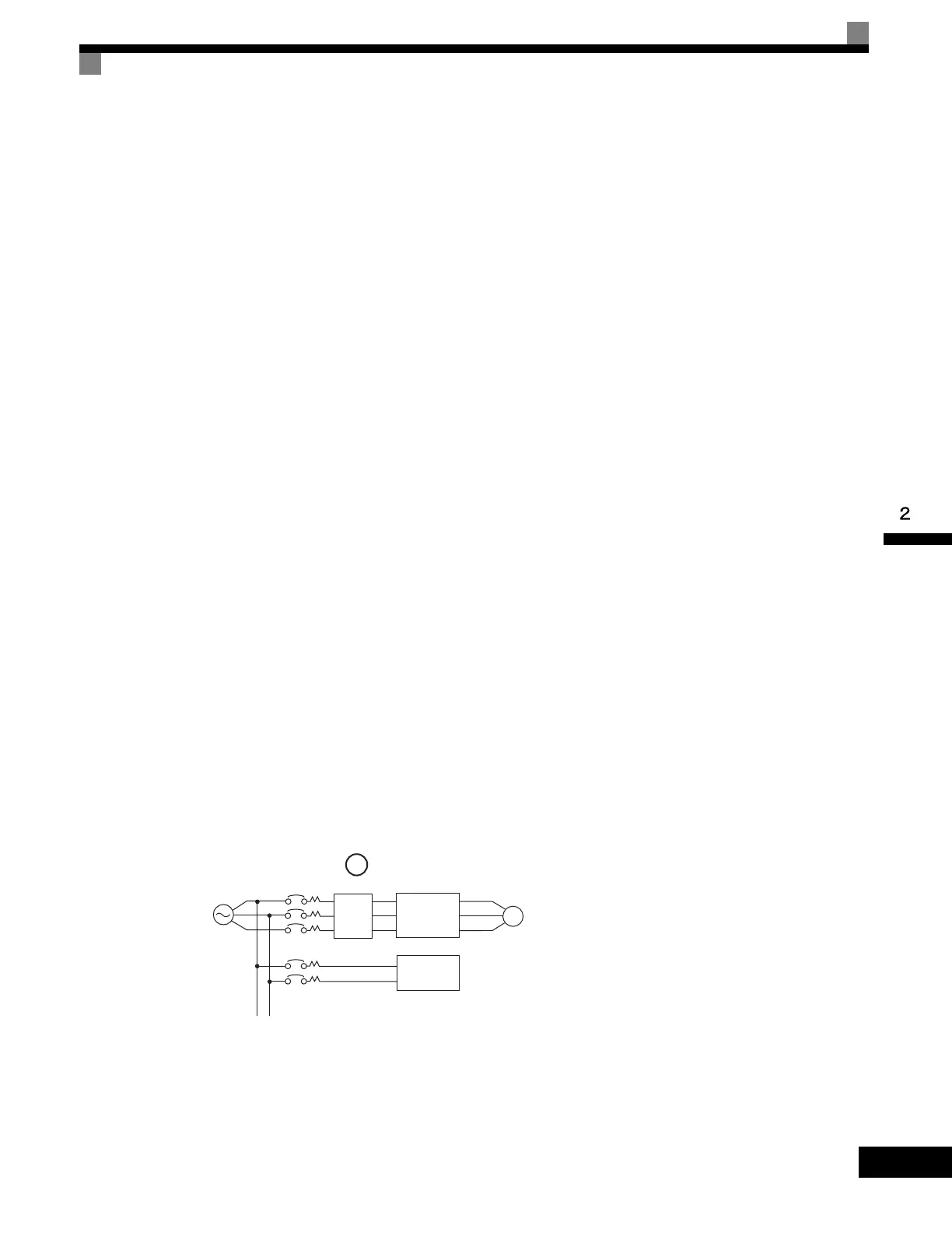
• Correct Noise Filter Installation
Fig 2.6 Correct Power supply Noise Filter Installation
Power
supply
Noise
filter
Drive
Other
controllers
Use a special-purpose noise filter for Drives.
Artisan Technology Group - Quality Instrumentation ... Guaranteed | (888) 88-SOURCE | www.artisantg.com

 Loading...


