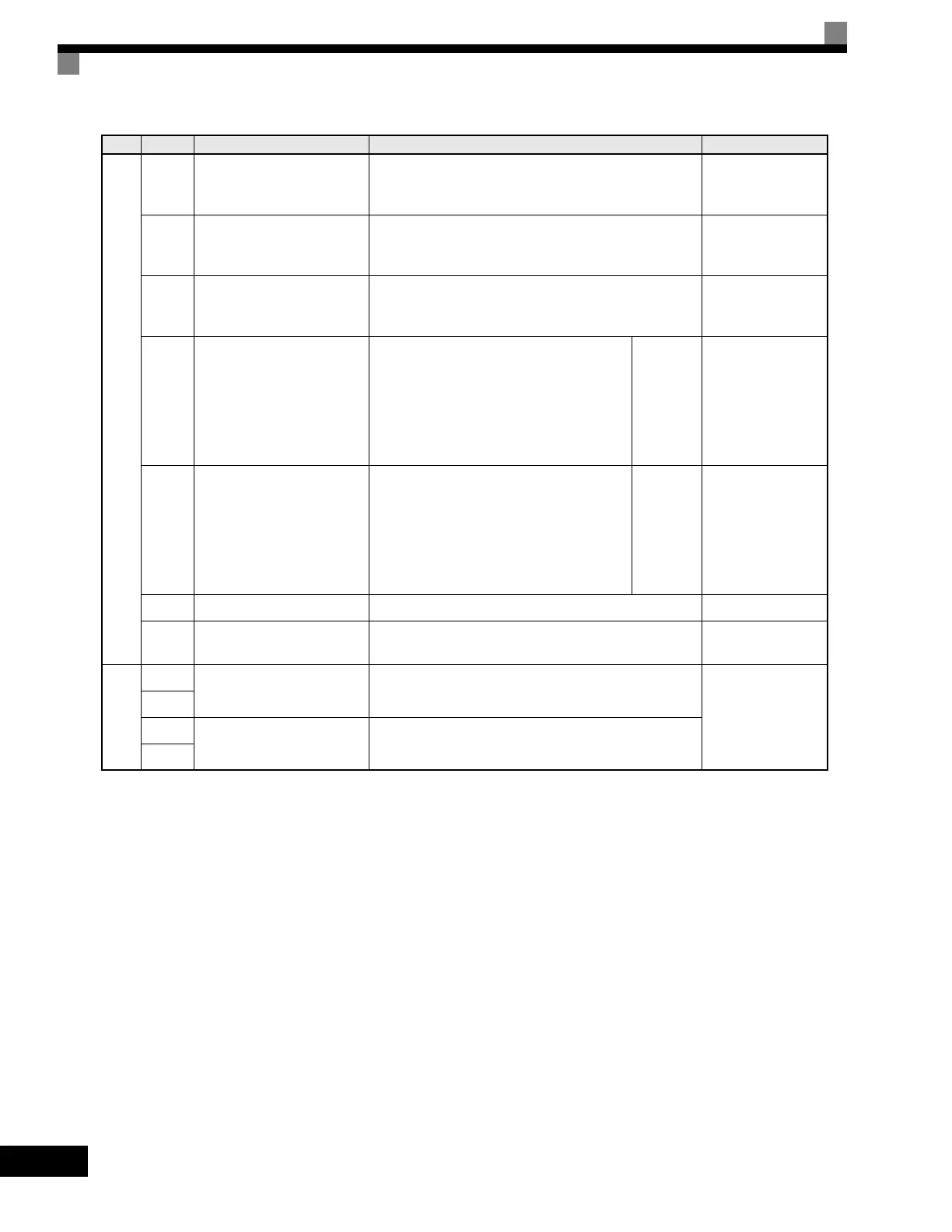
2-24
Analog
input
signals
+V +15 V power output
+15 V power supply for analog input
or transmitters
+15 V
(Max. current: 20
mA)
-V -15 V power output
-15 V power supply for analog input
or transmitters
-15 V
(Max. current: 20
mA)
A1
Master speed frequency
reference
-10 to +10 V/-100 to 100%
0 to +10 V/100%
-10 to +10 V, 0 to
+10 V (Input imped-
ance: 20 kΩ)
A2 Multi-function analog input
4 to 20 mA/100%, -10 to +10 V/-100 to
+100%, 0 to +10 V/100%
Multi-
function
analog
input 2.
Function
set by
H3-09
4 to 20 mA (Input
impedance: 250 Ω)
A3 Multi-function analog input
4 to 20 mA/100%, -10 to +10 V/-100 to
+100%, 0 to +10 V/100%
Multi-
function
analog
input 3.
Function
set by
H3-05
4 to 20 mA (Input
impedance: 250 Ω)
AC Analog reference common 0 V -
E(G)
Shield wire, optional ground
line connection point
--
Photo-
coupler
outputs
P3
Multi-function PHC
output 3
Factory setting: Ready for operation when CLOSED.
50 mA max. at 48
Vdc
*2
C3
P4
Multi-function PHC
output 4
Factory setting: FOUT frequency detected when
CLOSED.
C4
Table 2.10 Control Circuit Terminals (Continued)
Type
No. Signal Name Function Signal Level
Artisan Technology Group - Quality Instrumentation ... Guaranteed | (888) 88-SOURCE | www.artisantg.com

 Loading...


