6.1
SVB-01 Module Control Block Diagrams
6-15
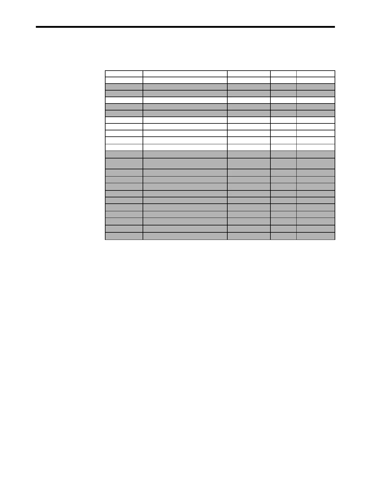
[ b ] Setting Parameters
No. Name Setting Unit Default Value Setting Range
OW
00
RUN Commands
− 0000h Bit setting
OW
01
Mode 1
− 0000h Bit setting
OW
02
Mode 2
− 0000h Bit setting
OW
03
Function 1
− 0011h Bit setting
OW
04
Function 2
− 0033h Bit setting
OW
05
Function 3
− 0000h Bit setting
OW
08
Motion Command
− 0 0 to 26
OW
09
Motion Command Options
− 0000h Bit setting
OW
0A
Motion Subcommand
− 0 0 to 65535
OL
0C
Torque Reference
Depends on torque unit. 0
−
2
31
to 2
31
−
1
OW
0E
Speed Limit at Torque Reference
0.01% 15000
−
32768 to 32767
OL
10
Speed Reference
Depends on speed unit. 3000
−
2
31
to 2
31
−
1
OL
14
Positive Side Limiting Torque Setting at the Speed
Reference
Depends on torque unit. 30000
−
2
31
to 2
31
−
1
OL
16
Secondary Speed Compensation
Depends on speed unit. 0
−
2
31
to 2
31
−
1
OW
18
Speed Override
0.01% 10000 0 to 32767
OL
1C
Position Reference Setting
Reference unit 0
−
2
31
to 2
31
−
1
OL
1E
Positioning Completed Width
Reference unit 100 0 to 65535
OL
20
Positioning Completed Width 2
Reference unit 0 0 to 65535
OL
22
Deviation Abnormal Detection Value
Reference unit
2
31
−
1 0 to 2
31
−
1
OW
26
Position Complete Timeout
ms 0 0 to 65535
OL
28
Phase Compensation
Reference unit 0
−
2
31
to 2
31
−
1
OL
2A
Latch Zone Lower Limit
Reference unit
−
2
31
−
2
31
to 2
31
−
1
OL
2C
Latch Zone Upper Limit
Reference unit
2
31
−
1
−
2
31
to 2
31
−
1
WWW.NNC.IR