9.1
Controlling Vertical Axes
9-3
9.1.2 Connections to
Σ
-
II
and
Σ
-
III
SERVOPACK
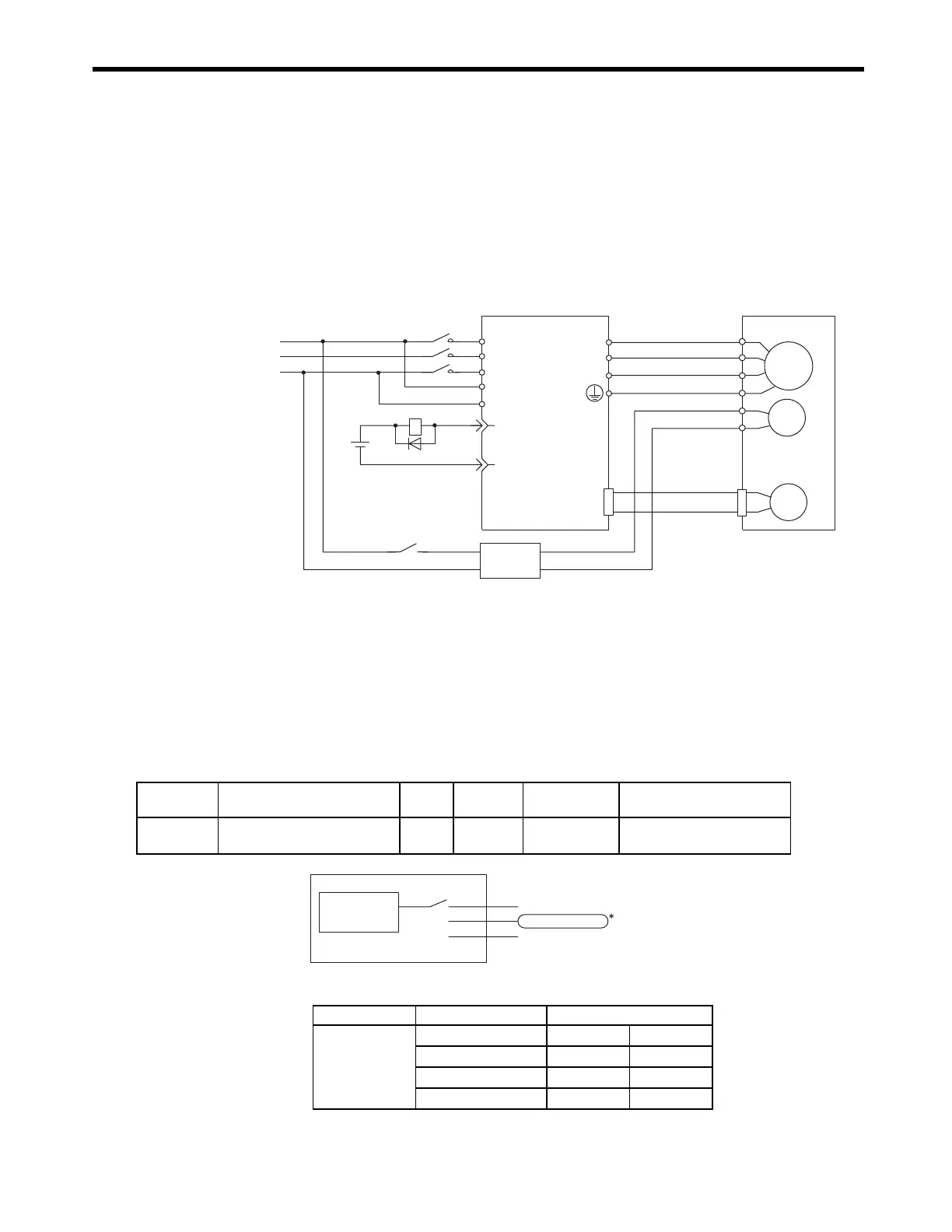
( 1 ) Connection Example
A circuit is configured to turn the brake ON and OFF using the /BK contact output signal from the
SERVOPACK and a brake power supply. The standard connections are shown in the following
diagram.
* 1. The output terminal is allocated using parameter Pn50F.2.
* 2. Brake control relay contact
* 3. There are 200-V and 100-V brake power supplies.
( 2 ) Parameter Settings
[ a ] PN50F.2 (Output Signal Selection 2)
The following parameter determines which pin of CN1 will be used to output the /BK signal.
* Select which terminal is used to output /BK. (Set to 2 in this example.)
M
BK
PG
U
V
W
CN2
AC DC
BK-RY
+24 V
L1
L2
L3
L1C
L2C
27-
28-
/BK+
/BK-
A (1)
B (2)
C (3)
D (4)
E (5)
F (6)
BK-RY
∗
1
∗
1
∗
2
Red
Black
Blue or
yellow
White
Brake power supply
*3
Power supply
SGDH or SGDS
SERVOPACK
Servomotor
with a brake
Parameter Name Unit
Setting
Range
Default Control Mode
Pn50F.2
Output Signal Selection 2 − 0 to 3 0
Speed, torque, position
control
Parameter Setting Output Terminal (CN1)
Pn50F.2
0 −−
12526
22728
32930
Pn50F.2
1
2
3
CN1-25, 26(SO1)
CN1-27, 28(SO2)
CN1-29, 30(SO3)
Output Terminals
/BK brake
interlock output
WWW.NNC.IR