2
Module Specifications and Connections
2.1.3
Module Connections
2-8
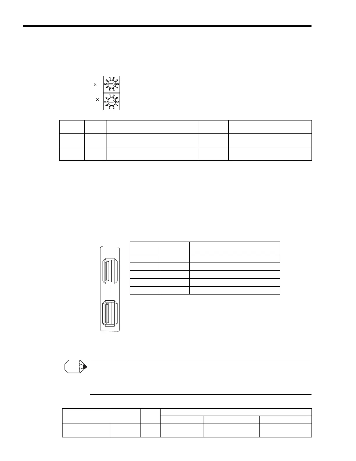
[ b ] Rotary Switches
This rotary switch is valid only in Slave Mode. It will be ignored in Master Mode.
2.1.3 Module Connections
This section explains the connections for the SVB-01 Module.
( 1 ) Connector and Cable Specifications
■
Connectors
The MECHATROLINK-I/II Connectors (M-I/II) on the SVB-01 Module connect the SVB-01 to the
SERVOPACK and distributed I/O.
The MECHATROLINK-I/II Connectors (M-I/II) are shown in the following diagram.
• Two connectors are provided, but the communication line supports one channel only.
• When connecting the SVB-01 Module to the end of the network, connect a JEPMC-W6022
Terminator to the unused connector.
• Both the top and bottom connectors are the same, so either can be connected.
■
Connector Specifications
10
1
Name Status Operating Mode
Default
Setting
Details
×
10
0 to 9
Local station address when in Slave Mode
(10s digit)
0
Sets the 10s digit of the local slave
address.
×
1
0 to 9
Local station address when in Slave Mode
(1s digit)
1
Sets the 1s digit of the local slave
address.
Pin No.
Signal
Name
Description
1
(NC)
Not used.
2
/DATA
Signal
−
3
DATA
Signal +
4
SH
Not used.
Shell
Shield
Connects the shield wire.
M-I/II
CN1
CN2
INFO
Name
Connector
Name
No. of
Pins
Connector Model
Module Side Cable Side Manufacturer
MECHATROLINK
Connector
M-I/II
4
USB-AR41-T11 DUSB-APA41B1-C50 DDK Ltd.
WWW.NNC.IR